
How can you establish a short circuit problem? The most common indicator that the circuit is not complete is when the circuit breaker trips.
A short circuit is an electrical circuit in a device that permits current to flow along an intended path with minimal or no electrical impedance. Usually, it is a result of excessive current following through the circuit.
Electricians use the term short circuit to speak of a state where a hot wire that carries live current comes into contact with a neutral wire. When this occurs, resistance lowers immediately and a high capacity of current streams through an unlikely path. A ground fault is a short circuit that happens when a hot wire transmitting current corrodes with some grounded portions of any given system.
Causes of short circuits
Various reasons for a short circuit commonly known are:
- Wire insulation with a broken circuit; Damaged or old insulation wires can allow hot or neutral wires to come into contact with each other. In return, this may cause a short circuit.
- Wire connection that is loose
- A wiring appliance that is damaged
Once you have suspected that you have a short circuit problem, there is a basic procedure you can follow to identify the location of the problem.
- Locate the circuit breaker that has gone off
- Inspect all power cords that connect to the circuit breaker that has tripped
- Turn off all appliance switches and lights that are alongside the tripped circuit breaker, then switch it back on
- Switch on each appliance socket or light one after the other until you get to the circuit that has a short.
- Check the problem of the circuit or the wiring using a multimeter.
Here, you can either use a digital or an analog multimeter to measure resistance, voltage, and current.
Measuring resistance of a short circuit using an analog multimeter
Resistance is usually the testing of opposition to electric current. The steps to follow are as follows:
- Locate the short circuit. It may either be in the wall wiring or the circuit breaker.
- Plugin the probes into the multimeters ports. Usually, the multimeter will have separate ports for the test. Plugin the probes in the right ports. They can be labeled COM, and in others, you could find the ohms sign.
- Select the required range. It is necessary to select range in an analog multimeter to obtain the best readings. Usually, the switch shows the maximum readings for resistance.
- Reset your multimeter to zero readings. Short circuit the circuit by placing the probes together.
- Read the measurement on your multimeter.
- Switch off the multimeter. It is advisable to switch off the multimeter function switch to a higher voltage range once the resistance measurement is complete.
Measuring resistance using a digital multimeter
Using a digital multimeter is easy and fast, as there is no zeroing as in an analog multimeter. Here are the steps to follow in measuring resistance using a digital multimeter:
- Position the switch to read the maximum reading
- Plugin the probes in the required ports. The multimeter has several ports, which might be labeled as COM or with the ohms sign.
- You can now switch on the multimeter.
- Next is to select the range. This is to aid you in obtaining the best reading. Choose a range where the estimated resistance value is below, but close the highest range
- Take the measurement. Apply the probes to the wires that are under test. If necessary, the range can be changed.
- Switch
off the multimeter, to save energy. It is advisable to rotate the
function switch higher voltage range before switching off.
Measuring current with an analog multimeter
The steps to follow in measuring current are:
- Insert the probes into the voltage sockets on the multimeter.
- Switch on the multimeter to measure current.
- Enhance the range to get the most accurate reading. Adjust the multimeter to the highest deflection.
- Return the probes into the voltage measurement ports. Turn the range to the highest voltage point before switching off
Measuring current using a digital multimeter
- Turn on the multimeter.
- Insert the probes into the correct connection. In this case, use the resistance sockets.
- Set the multimeter switch to measure current. Ensure the highest range goes above the anticipated reading. Avoid overloading the meter by selecting a range that is too high.
- Note down the readings on the multimeter.
- Switch off the multimeter to save power.
Note that on measuring, the current power should be on.
Measuring voltage using an analog multimeter
- Plugin the probes into the negative and positive ports of the multimeter.
- Set the range to put up with the highest anticipated value that allows a little more as harm could occur due to high voltage.
- Ensure that the red lead is pointing the live lead.
- Probe the maximum voltage point with the live lead probe.
- Check to achieve the positive rebound of the multimeter. To obtain the most accurate readings, adjust the multi-user range switch to minimize the range until the highest deflection is read on the multimeter.
- Note down the readings
- Make the next measurement or unplug the probes when done with the test.
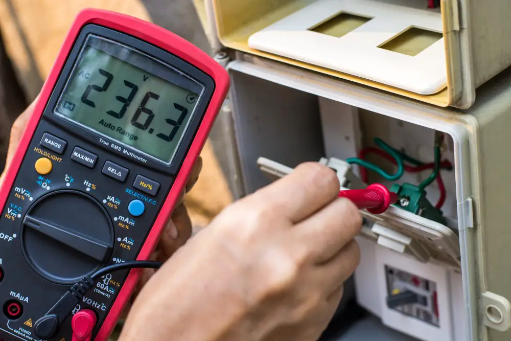
Measuring voltage using a digital multimeter
- Plugin the probes into the resistance ports on the multimeter.
- Switch on the multimeter.
- Set the meter range to accommodate the highest expected value.
- First, probe the low voltage points.
- Probe the higher voltage points.
- If necessary, adjust the range switch to obtain the best readings.
- Note down the readings.
- Do the next reading or turn off the meter if done.
Conclusion
The significant difference between the two multimeters how they display their readings. The digital multimeter displays its readings in digits mostly on LED or LCD screens. The digital multimeter is also easy to use. Hopefully, this article will be of help to you as it has explained what to measure in a short circuit using an analog or a digital multimeter.