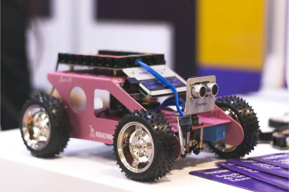
Have you ever been fascinated by a remote controlled car, or better yet, wondered how it was made? Well, such has been the case with many people who’ve grown around electronically controlled devices.
The element of control has been with us since our childhood and most of us have fantasized about controlling cars, airplanes, ships, and trains, among other things.
Therefore, it isn’t a surprise when we grow up and grow some curiosity on how to actually build and control some appliances. It’s a practice most of us fell in love with even before understanding what it meant. So, back to our main question, which is how to make a Bluetooth car with Arduino?
Arduino has rapidly become one of the most preferred microcontroller platforms for creating interactive projects. The tool has grown in popularity and gained admiration for every level of user in its community.
This is because it’s relatively affordable compared to other circuit boards, easy to design or code programs, and offers both an open-source software and hardware platform.
Besides that, Arduino is licensed under Creative Commons, meaning interested users of any level are free to design and program their own projects from the module. And in this project, you’ll learn how to make a Bluetooth car with Arduino.
It’s actually one of the most important projects to undertake once you are through with the basics. In this project, Bluetooth and Arduino remains from the core of the robot controlled car, among other essential components detailed below.

What You’ll Need
- Arduino Uno
- Robot/Car Chassis (with a base, BO motors, and wheels)
- HC-05 Bluetooth Module
- L298N Motor Driver Module
- Power Supply
- Battery Compartment
- 4 x 5V Geared Motors
- Connecting Wires
- And a Smartphone with a Bluetooth Controller App
After acquiring the above mentioned components, designing the circuit should be the next step. But first, let’s have a bit of constructive knowledge about the Bluetooth and Motor Driver Modules.
L298N Motor Driver Module
As the name suggests, the L298N Driver Module supplies the needed drive current to the motors of the Arduino remote controlled car.
HC-05 Bluetooth Module
This is the other essential Module in the circuit and it allows the Arduino to communicate with your Smartphone via Bluetooth.
Designing the Circuit
Onto the design of the Bluetooth circuit, the first part to consider is the HC-05 Bluetooth Module. Thereafter, you connect the +5V and GND pins of the Bluetooth Module to the +5V and GND of the Arduino board.
And because this project only aims to transmit data related to the Robot’s movement from a Smartphone to the HC-05 Bluetooth Module, you’ll only connect together the TX pin of the Bluetooth Module to the RX Pin of the Arduino.
This RX pin of Arduino is based on the Software Serial library (Pin 2 and Pin 3 are configured as RX and TX on Arduino). The RX pin of the Bluetooth is left open.
The next step is working on the L298N Module. Here, you’ll configure Digital I/O Pins 9 through 12 of Arduino as Input pins of the Motor Driver and connect them to the IN1 via the IN4 of the L298N Module. You’ll need to connect both Enable Pins to 5V through the provided jumper.
In this project, the Bluetooth controlled RC comes with 4 geared motors. And because the L298N Motor Driver Module only has two motor slots, you’ll have to merge the left and right motors as single sets each. Afterward, connect both these sets to the L298N Motor Driver Module output.
Connect the components! 🙂

Code Required
#include
#define IN1 9
#define IN2 10
#define IN3 11
#define IN4 12
//#define EN1 6
//#define EN2 5
SoftwareSerial mySerial(2, 3); // RX, TX
String data;
int btVal;
void setup()
{
//Serial.begin(115200);
pinMode(IN1, OUTPUT);
pinMode(IN2, OUTPUT);
pinMode(IN3, OUTPUT);
pinMode(IN4, OUTPUT);
//pinMode(EN1, OUTPUT);
//pinMode(EN2, OUTPUT);
digitalWrite(IN1, LOW);
digitalWrite(IN2, LOW);
digitalWrite(IN3, LOW);
digitalWrite(IN4, LOW);
//analogWrite(EN1,63);
//analogWrite(EN2,63);
mySerial.begin(9600);
}
void loop()
{
while (mySerial.available()){
{ data = mySerial.readStringUntil('\n');
//Serial.print(str);
}
btVal = (data.toInt());
//Serial.print("BlueTooth Value ");
//Serial.println(btVal);
switch (btVal)
{case 1:
//Serial.println("Forward");
forward();
break;
case 2:
//Serial.println("Reverse");
reverse();
break;
case 3:
//Serial.println("Left");
left();
break;
case 4:
//Serial.println("Right");
right();
break;
case 5:
//Serial.println("Stop");
stoprobot();
break;
}
}
if (mySerial.available() < 0)
{
//Serial.println("No Bluetooth Data ");
}
}
void forward()
{
digitalWrite(IN1, HIGH);
digitalWrite(IN2, LOW);
digitalWrite(IN3, HIGH);
digitalWrite(IN4, LOW);
}
void reverse()
{
digitalWrite(IN1, LOW);
digitalWrite(IN2, HIGH);
digitalWrite(IN3, LOW);
digitalWrite(IN4, HIGH);
}
void left()
{
digitalWrite(IN1, LOW);
digitalWrite(IN2, LOW);
digitalWrite(IN3, HIGH);
digitalWrite(IN4, LOW);
}
void right()
{
digitalWrite(IN1, HIGH);
digitalWrite(IN2, LOW);
digitalWrite(IN3, LOW);
digitalWrite(IN4, LOW);
}
void stoprobot()
{
digitalWrite(IN1, LOW);
digitalWrite(IN2, LOW);
digitalWrite(IN3, LOW);
digitalWrite(IN4, LOW);
}
Finalizing the Project
At this point, you should assemble the Bluetooth car and make the necessary final connections. What follows next is uploading the above given code to the Arduino.
Now, take your phone and in the Android App, use five (5) keys as follows:
- Forward
- Reverse
- Left
- Right
- Stop
The corresponding data of each key follows the following structure:
- Forward – 1
- Reverse – 2
- Left – 3
- Right – 4
- Stop – 5
Once you press a key, the corresponding data gets transmitted to the HC-05 Bluetooth Module from the Smartphone via Bluetooth compatibility. Now, within the Arduino code, the board receives the data coming from the Bluetooth Module and the commanded instructions as per the keys pressed.
In conclusion, you should know that there are some limitations that come with this project such as the Bluetooth range and sufficient power to the Modules. The maximum Bluetooth range is 10 meters and any distance beyond this from the RC car will disconnect the Bluetooth connection.
Additionally, you have to ensure that there is sufficient power supply, especially to the Bluetooth Module for optimum functionality. You will experience connectivity issues when the power supply is low.


