Relay is a switch which is electrically operated and can be switched on and off allowing current to flow through or not. Relays can be controlled with low voltage as well. One of the vital things you might consider doing with your Arduino is controlling high voltage devices with volts of approximately 120 to 240 volts such as lights, fans and heaters, among other appliances.
Usually, Arduino has been designed to operate at 5 volts; this means that you cannot use it to control devices with higher voltage directly. However, you can use a 5-volt relay to help in switching 120 to 240-volt current and use an Arduino to control your relay.
You can program your Arduino switch on your relay when specific events occur; for instance, when thermistor temperatures get more than 30 degrees or when a photoresistor’s resistance goes lower than 400 Ohms. You can use any sensor to trigger a relay to go off or on. The best part is that the trigger does not have to be obtained from sensors. This means that it is capable of occurring at particular time intervals and you can trigger it from pushing a button or when you receive an email.
In this article, we shall be showing you how to use a relay with an Arduino. We shall be using SRD-05VDC-SL-C 5V relay since it is the most popular among DIY hobbyists and Arduino.

Using Relay with an Arduino
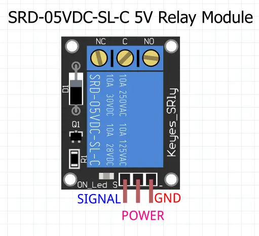
This is one of the commonly used relays and it is equipped with three different high-voltage terminals which are NO, NC and C. These terminals are often connected to any device that you would like to control. On the other side, this relay is equipped with three low volt pins which are VCC, Ground, as well as Signal that are often connected to an Arduino.
Point to note
- The NC terminal is commonly known as Normally Closed, and it has a voltage range of 120 to 240 volts.
- On the other hand, the NO terminal refers to Normally Open, and it has a voltage range of 120 to 240 volts.
- The C terminal is the Common terminal
- On the other side, the Ground terminal is usually connected to Arduino’s ground pin.
- 5V VCC is connected to the 5V pin of an Arduino
- Last is the Signal terminal which has been designed to carry trigger signals from an Arduino when activating a relay.

Usually, the relay’s inside is equipped with a 120 to 240-volt switch which is joined with an electromagnet. The electromagnets usually become charged and start moving switch contact closed or open once the relay gets a high signal in a signal pin.
Normally Open terminal vs. a Normally Closed terminal.
As by now you probably understand that there are two designs of electrical in a relay; the Normally Open terminals and the Normally closed terminals. Choosing a terminal to use will highly depend if you would like 5 Volt signal to switch off or on.
Usually, the 120 to 240-volt switch supplies current which will enter your relay at C terminal or common terminal in the configurations. In order for you to operate a Normally Open contact, you will have to use NO terminal. On the other hand, in order to use a Normally Closed contact, you will have to use NC terminal.
The Normally Open terminal
In a Normally Open terminal, whenever the relay gets a high signal a 120 to 240-volt switch will close and then allow the flow of current from a C terminal into NO terminal. In addition to that, the low signal will deactivate a relay as well as stop the current. Therefore, if you would like turning on your relay using a high signal, you will have to use a Normally Open terminal.
The Normally Closed terminal
When it comes to a Normally Closed terminal, the high signal will open up a switch and then interrupts the current of 120 to 240 volts. The low signal will close your switch allowing the flow of current from terminal C to NC terminal. Thus, if you would like a high signal which helps turn off a 120 to 240-volt current, you should consider using a Normally Closed.
Relay circuit that controls the temperature
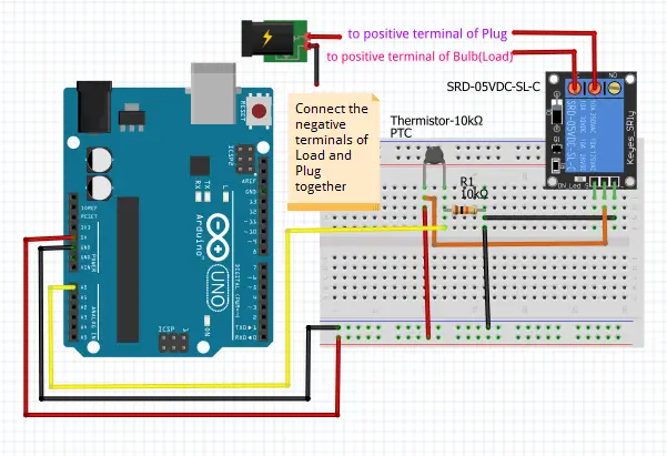
To better understand how to use a relay with an Arduino, we shall take you through a temperature-controlled circuit which turns off the light bulb whenever a thermistor’s temperature reaches 150 degrees Fahrenheit. Usually, thermistors are ideal for use with 5 Volt relays. Furthermore, you might consider turning off a large motor whenever it becomes very hot or switches on your heater when the temperature becomes cold.
This setup is relatively easy; all you have to do is ensure that a high voltage connection to your relay is secured. When doing so, you will have to identify hot or power wires, which are often red in color in a cord that leads to your bulb light and then cut it.
The side that heads to your bulb should be connected to a NO terminal in your relay. The C terminal should be connected with the side that leads to a plug.
By doing so, your relay will be on the hottest side, then the current will be switched before reaching a light bulb. Putting a relay on a neutral wire is highly dangerous because when your device fails, the current will end up falling to the ground when your relay goes off.
The part of a circuit in the thermistor will be set like a voltage divider. Therefore, the resistor’s value has to be of equal value as a thermistor; for instance, when using 10KOhms thermistor, your resistor has to be 10KOhms as well.

Final Thoughts
Using a relay with an Arduino is relatively easy, and anyone can do it irrespective of their skill level. To achieve this successfully, you should consider adhering to the tips discussed in this article. As we come into conclusion, we hope that you find this article helpful as you try to use a relay with an Arduino.

