With an LCD module, you will be able to make your embedded system independent. By doing so, it will take both digital as well as analog inputs on the input pins and then display all the corresponding outputs on the screen. In addition to that, you will be able to use it in generating other types of outputs.
Usually, LCD outputs feature various sizes, including a display that is single line monochromic as well as a display with a large graphic color display. Both of these designs use almost one method when it comes to displaying data.
When it comes to Arduino, you can use it as the stand-alone board in which inputs and outputs are given or taken from your board. In addition to that, the Arduino board is equipped with numerous ports for communications; however, they often don’t match when it comes to the effectiveness offered by an LCD module. An LCD module is designed to eliminate requirements for a PC or a device that is connected to the Arduino board in order for the data to be sent by your board.
An Arduino board is not equipped with an in-built LCD module that will aid in displaying data. This means that you will have to connect it to an external LCD module to aid in displaying vital data such as sensor, temperature, and strings, among others.
The Arduino IDE library aids in accessing your LCD model with the utmost ease. Therefore, in this article, we shall be discussing how to use Arduino to display sensor value on LCD.

Displaying sensor value on LCD using Arduino
Several displays are equipped with 16 pin interfaces that are numbered from 1 to 16. On such displays, connectivity code is often printed on the circuit board. You should note that a 220 resistor that is between 5 volts and pin 15 is ideal for reducing voltage to backlight LED to 3.3 volts.
Usually, 10kΩ pot meter is designed to act as a variable resistor between the 3rd pin and GND, offering a fine-tune. It operates perfectly without having to be connected to 5 volts.
These types of displays feature different colors, tastes, along with the number of characters to be displayed. It would be best if you considered working with 16 by 2 monochromic displays since it is considered as the best LCD in the market. In addition to that, they are said to be ideal newbies, and they serve as the perfect need for an advanced hobbyist of the Arduino.
Connecting potentiometer
Before connecting your LCD to Arduino, you should consider installing a potentiometer. The pin 3 of your LCD will be connected to the middle contact named wiper using a 10kΩ potentiometer.
You will only connect one of the two pins of your potentiometer to GND and then ignore the remaining pin. The pot meter will help in supplying voltage to your LCD hence adjusting the contrast of characters against its background. The power for background lighting is transferred through pin 15 as well as 16 of your LCD.
You will achieve background lighting with the help of white led along with diffuser. This diffuser will stick out; since led is a 3.3-volt device, you will require a 220 resistor in this series connected at the 15th pin to help in protecting the backlight led against excess power.
A potentiometer is ideal for use in fine-tuning LCD contrast; you experiment by connecting it to the 3rd pin through a resistor along with a fixed value and GND of your Arduino. You will have to start the experiment using a 10kΩ resistor and then start replacing it stepwise, each one using a lower value until you achieve satisfactory.
Connecting LCD to Arduino
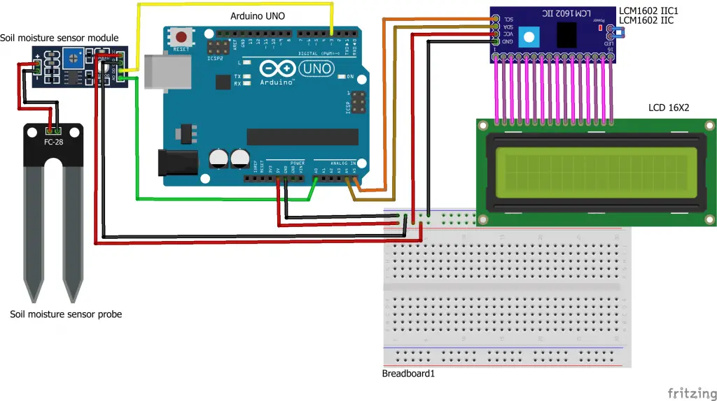
When it comes to connecting LCD to Arduino, the 1st and 2nd pin of an LCD screen will be reserved for power. The GND will be connected to pin 1 afterward, 5 volts will be connected to in 2. On the other hand, pin 3 will be receiving power from your potentiometer, and pin 4 will be connected to the 12th pin of your Arduino.
Pin 6 of your LCD will be joined with pin 11 of your Arduino. The data sent by Arduino will be displayed on your LCD screen with the help of pin 11, 12, 13 as well as 14 of your display. Your 11th pin of the display will be connected to the 5th pin of your Arduino. LCD pin 12 will be connected with Arduino’s pin 4, and the display pin number 13 will be connected to Arduino’s pin 3. With that in place, the last LCD pin 14 will be connected to pin 2 of your Arduino.
When connected correctly, you will be able to display data from your Arduino on to the LCD screen with the utmost ease. Usually, the pins can be connected using Dupont wires; you might as well consider soldering the wires. However, in a prototype phase, you should consider using a breadboard.
Connect the components! 🙂

Testing the LCD screen display
You will require a basic sketch that will help you bring your LCD screen to life. When you have the LCD pins connect correctly to the Arduino, you should consider double-checking it to before you continue. Once it is set accordingly, you will connect your Arduino to a computer and use appropriate code to run it. Compile and upload the sketch to help you test your LCD screen display.
Usually, the sketch will commence with reference to the library. The library will be supplied by your Arduino IDE. This means you don’t have to worry about searching or downloading it from the net. You will be able to assess the functionality of your LCD screen with the utmost ease.
Final thoughts
Using Arduino to display sensor value on LCD is not a complicated task. With the correct code and hardware, this process will be achieved within no time. Adhering to the tips discussed in this article will help you boost your chances as a newbie to use Arduino to display sensor values on LCD.

