
When it comes to technology there are many technical aspects that a person should learn. This can affect the signals and the output of certain devices. Many people wonder what an analog in Arduino is.
There is some information to help make this more clear and easy to understand. The Arduino can input and output the analog signals. It is able to do the same with the digital signals.
Analog Signal and the Different Values
The analog signal can take on many different values. It is a little different than some of the digital systems. There are two values that it has. This includes the high and the low. There is a way that the values of the analog signal can be measured. To be able to measure the analog the Arduino has some built-in features that can help. There is an analog that is built-in and an analog to digital converter. This will be able to turn the analog voltage into a digital value.
There is a specific reason behind this function. The analog read pin is the function and the value that a person will get from this reading. This will also convert the value of the voltage on the analog input pin. The value that will be turned will range in a specific reading.
The value will run from 0 to 1023 which will be a reference value. The default reference is around 5V for the Arduino boards and it can be around 3.3 V for Arduino boards. There is only one parameter for the pin number.
Arduino Converter
The Arduino does not come with a built-in digital to analog converter or a DAC. It is able to use a pulse width modulation or a PWM. This is a digital signal that can be used to get some of the functions from the analog Write. The pin number can be used for the PWM output. If the value number is equal to 0 then the signal is going to be off. It will not even be close and will need some serious attention. If the value can reach 255 then the signal is going to be on.
On the average Arduino board, the PWM function will have some pins including 3, 5, 6, 9, 10, and even 11. This frequency of this signal is around 490Hz on average. On the Uno and related boards, the pins 5 and 6 have a frequency that is able to reach 980Hz. The Pins 3 and 11 will run at 980 Hz.
Diagram 🙂


Control the Brightness of the LED
TThe PWM signal can be used to control the brightness of the LED. To do this the Arduino is going to be needed. To help control the brightness level the LED has to be connected to digital pin 2 of the Arduino. The program will vary based on the cycle of the PWM that is controlled by analog pin A0. A code is then put into the system and a person will be able to control the brightness of LED using their Analog input of Arduino.
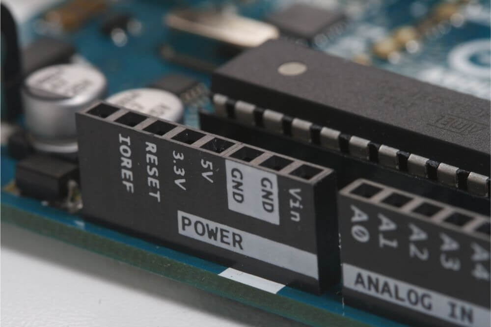
Pins
Some other parts of the Arduino Analog are needed. The Analog pins are marked with some letters. They are marked with the letter A and then they have numbers that follow them for example there is A1, A2, and so on. Only the Analog pins can be used to measure the analog signal. If more channels are needed then the ADC can be used. A person should check the guidelines to make sure everything fits.
Resolution
When working with the Arduino ADC Resolution there are some things to keep in mind. There is often a 2-bit resolution that has a reference of 4 volts. The ranges for this will be between 0 and 1024. The Arduino has an ADC that has a 10-bit resolution to handle all of this power and work with the different bits.
Some boards are going to have a different voltage that a person should pay special attention to. There is the Arduino board including the Uno, Mega boards, and related that have a standard operating voltage of 5V. This is something to keep in mind when setting up the board.
Voltage
When setting up the Arduino analog result there is some voltage and output information that needs to be kept in mind to set things up properly. If the analog voltage is between 0 to 0.99 then the digital output will be 0. It will not be working in this case and some adjustments will need to be made. If the voltage is going to be between 1 and 1.99 there will be some output.
The digital output will then be at 1. If the voltage has been set at 2 to 2.99 then the output is going to be at 2. When the voltage has been increased from 3 to 3.99 the output will be at 3. If the voltage can reach 4 volts then the output is going to be 4.
The output is usually equal to the voltage that is being sent into it. Any numbers that do not fit into this pattern may be errors and a person may need to go back and check their analog to make sure that it is working properly. They will need to check the analog too.
Analog Signal Check
There is a way to measure this analog signal. A person should look at the analog pin A0 and connect this to the Arduino board. It will help provide a power source to this board. It will then be put in pin mode.
The voltage will then be multiplied by the int and this will give a person their analog read. If there is a problem with the pin and this number cannot be read a person will know that they have an error and may need to check their connection.
The Arduino Analog can handle a lot of power. A person should become familiar with the voltage if they are going to use this. They will allow them to get the best quality and keep everything working properly.