Interfacing a character Liquid Crystal Display commonly referred to as LCD to an Arduino, helps in adding a nice element of readability to any particular project.
Some of the best Arduino works across the globe, such as in sports, are equipped with LCD screens. You can use an LCD screen in displaying information from a sensor such as Arduino when connected to it.
Irrespective of the project you are working on, LCD screens are highly essential output devices for an Arduino. In this article, we shall be discussing how to connect Arduino to LCD. As a DIY enthusiast, you might consider using the tips discussed in this article and build an LCD screen Arduino project.

Overview
You should note that LCD screens are by far the easiest devices you can work with along with your Arduino in order to display information. Nevertheless, there are two types of LCD screens available; character LCD and graphical LCD. In this article, we shall be focusing on the character LCD since they are relatively easy to work with. In addition to that, when it comes to sizes, there different LCD sizes including:
- 16 columns by 2 rows, which is equivalent to 16 by 2 character LCD.
- 20 columns by 4 rows, which is equivalent to 20 by 4 character LCD.
Furthermore, they come in different colors which allow you to choose one that will best suit your needs such as:
- Blue with white characters LCD
- Green with black characters LCD
- Red with black characters LCD
In most cases, the blue and green LCDs are the most common, while the remaining colors can be relatively challenging to obtain.
Connecting Arduino to LCD
When it comes to connecting Arduino to LCD, the first thing you will have to do is soldering 16 pin male headers on your LCD. Once that is done, you might consider using a female connector or a 16 pin female header in order to connect to the Arduino. If this is your first time to interface an Arduino, you should consider using a breadboard since it is relatively easy.
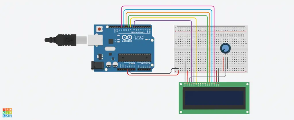
Before you start working on your LCD, you should consider checking it. In order to do this, you should connect pin 15 on your LCD to the 5V pin of your Arduino. Once that is done, you will go ahead and connect your LCD pin 16 to the GND pin of the Arduino. Usually, these pins are ideal for powering up the backlight of the LCD.
With that done, you will go ahead and set up the logic for LCD. To achieve that, you should consider connecting the LCD pin 1 to the GND pin of your Arduino. With that done, you should connect the LCD pin 2 to the 5V pin of your Arduino. The next step is to set up a contrast adjusting potentiometer.
To do that, you will take a 10K potentiometer and then connect its first terminal to the 5V pin of your Arduino and then the second terminal, which is the middle pin, should be connected to pin 3 of the LCD, and the last terminal should be connected to GND pin of the Arduino.
With that done, you will go ahead and power up your Arduino. Once it’s one, the backlight of your LCD will turn on. Furthermore, when the knob of your potentiometer is turned, the character blocks that are displayed on your LCD screen will either turn dim or bright.
When this occurs, it shows that your LCD screen has been connected successfully. Otherwise, if you fail to achieve this, you should consider counter checking the connections and potentiometer.
Once you confirm that the LCD has been connected correctly, you will connect data lines and other pins that work with an LCD. It would be best if you considered starting by connecting the control wires for your LCD.
Start by connecting pin 5, which is (RW) of your LCD, to the GND pin of your Arduino; usually, this pin serves as the Write or Read in. Proceed to connect RS or pin 4 of your LCD to the digital pin 7 of your Arduino.
Usually, the RS pin helps in telling an LCD whether you are sending data or a command. This allows it to change the cursor’s position. With that done, you go ahead and connect EN or pin 6 of your LCD to pin 8 of your Arduino. The EN pin acts as an enable pin on your LCD, and it is often used in telling an LCD that the data is ready for reading.
The next thing you will have to do is to connect four data pins on your LCD. To do this, you will go ahead and connect DB7 or pin 14 of your LCD to the digital pin 12 of your Arduino. Once that is done, you will proceed to connect DB6 or pin 13 of your LCD to the digital pin 11 of your Arduino. The next step is connecting DB4 or pin 11 of your LCD to digital pin 9 of your Arduino.
With that done, you will have complete wiring up your LCD to Arduino successfully. Once you are through, you will see four unconnected pins between the control pins and data pins on your LCD.
Connect the components! 🙂

Coding
When you are done with connecting your LCD to Arduino, you might try and display anything on your LCD via the Arduino. However, before doing that, you will be required to download the LiquidCrystal library. Set it up and then proceed to open your Arduino IDE and upload your code to the Arduino. Once that is done, you will be able to see a display on your LCD connected to the Arduino.
Final Word
Connecting Arduino to LCD is relatively easy, and it can be achieved by any individual irrespective of their level of skill. By following the tips discussed in this article, you will come to find out that connecting Arduino to LCD is a breeze. As we conclude, we hope that you find this article helpful as you connect your Arduino to LCD.


