So you want to learn about how to cycle through different LEDs on your Arduino natively? You have come to the right place. Unleashing the power of loops and the random function in Arduino’s IDE will allow you to light up any display.
Think Christmas lights, art exhibitions, displays, and much more. We will show you five relatively simple ways of blinking LED lights with Arduino. The sequential blinking of LED lights is the “Hello World” of hardware programming.
Today we will make a simple LED flasher using Arduino (UNO). We will make use of a transistor circuit to make our LED flasher. The programming C code on Arduino makes it easy and fun. Here we go!

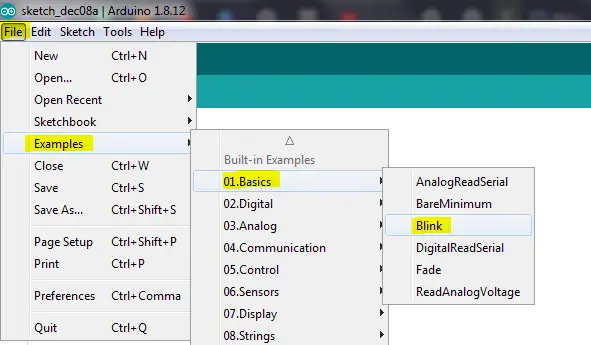
Blinking an LED with standard built-in
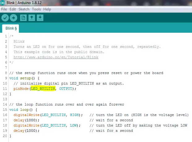
The standard built-in example that comes with the Arduino IDE is pretty straightforward. The LED_BUILTIN is a constant that contains the number of the pin connected to the on-board LED—on the Arduino Uno, designated as pin 13.
To begin, go to the setup function for the setting of the pin. Now do the following:
- Set the pin to high (5V) to turn on the LED.
- Wait for precisely one second.
- Now set the pin to low (0V) to turn the LED off.
- After another full second, repeat previous steps.


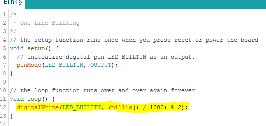
One-Line Blinking
Using a smart manipulation trick, you can take advantage of Arduino’s Millis () function trick and avoid calling delay. As Arduino runs, it will automatically return the number of milliseconds. Dividing the returned value by 1000 will give us the exact number of seconds passed.
Next, we take the number of seconds to calculate the remainder by dividing it by two. The modulus (%) operator determines values by displaying 1 for odd digits and 0 for even ones.
Simply put, we take the number of seconds passed since the program started running and set our LED values based on this data. Using this method, you will not only be able to achieve blinking but perform additional tasks inside your loop.
The one-line blinking method allows you to set blinking intervals every second, 1.26 seconds, or every 3 seconds.

Two Line Blinking
To achieve a two liner, all you need to do is toggle the value of the pin to cut the loop. Here is a code to put you on the right course:
Void setup() {
Pin mode(LED_BUILTIN, OUTPUT);
}
Void loop() {
Digital Write(LED_BUILTIN, !digital read(LED_BUILTIN));
Delay(1000);
}
The explanation is simple: Digital Read () returns the pin’s current output value as one if the pin is high and the LED turned on. If the opposite is true, then there is a zero value display. We can use the “!” (Not) operator to invert that value and manipulate the LED’s state.
In even simpler terms, the code above is interpretable as:
- Toggle LED state.
- Delay for one second and repeat.
Using Timers
So far, our solutions on how to make LED’s Blink in multiple ways with Arduino have demonstrated how to use its built-in functions. These methods will work on any board supported within Arduino’s environment. However, employing external hardware features like timers can also achieve a blinking effect.
Hardware timers link to their microcontrollers’ clock speed; This means intervals are predetermined and can register speeds in the millions per second range. The code below will help us set up Arduino’s hardware timers.
Void setup() {
  TCCR1A  and TCCR1B  both 0
  Bit Set (TCCR1B, CS12) ;  // 256 pre scaler
  Bit Set (TIMSK1, TOIE1); // timer overflow interrupt
  pinmode(LED_BUILTIN, OUTPUT);
}
ISR(TIMER1_OVF_vect) {
  digitalwrite(LED_BUILTIN, !digitalread(LED_BUILTIN));
}
void loop() {
}
Let us do some explaining here as some of the seemingly missing values and acronyms can get a little confusing:
First, the timers we have used here (a total of three UNO timers in this case) are numbered 0 through to 2. Both timers 0 and 2 are of the 8-bit variety, whereas timer 1 has double their capacity.
Each of the timers has unique CPU variables called registers that control them. Upon reaching their maximum values, depending on how fast each can count, timer one triggers the TCCR1A mentioned above and TCCR1B registers.
Next, we set a variable CS12 in the TCCR1B register. This flag informs the microcontroller to kick up the counter to the desired speed (256 clock cycles, or 16,000,000 / 256 = 62500 times a second in this case). The following line communicates with the CPU for the generation of hardware interrupts every time there is an overflow in the timer.
The interrupt service routine (ISR) is a hardware generated occurrence that brings up a predefined routine in the code. TIMER1_OVF_vect is a section of code that runs whenever there is an overflow from timer 1.
In a nutshell, our code sets a timer that goes up a given number of times every second. When the timer reaches a maximum value, the interrupt service routine runs and toggles the LED. The timer then resets to zero and begins the count all over again.
Hardware Triggered Blinking
In the hardware blinking method, we manipulate the hardware to do the toggling of the pin for us instead of running code every time. It does require more in-depth knowledge to pull it off but using hardware to get the blinking going is well worth it.
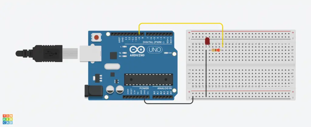
For starters, you will need to connect an LED to pin 9 of your board. It works by setting the OCR1A (timer one output register) to 62500 and enabling COM 1A0 flags to adjust a specific pin each time you hit the target value on the timer. As always, the timer then automatically resets to zero, to repeat the cycle.
Connect the Components! 🙂

A Quick Recap
Arduino is a versatile platform that allows us to get those creative juices flowing. Making Multiple LED’s blink is just but one of the many ways Arduino shows its mettle. Even when you need to perform multiple tasks within your loop, Arduino is customizable enough to get it done with ease.
Final Thoughts
We hope you now understand how to make multiple LED’s blink with Arduino from these five methods. With basic coding knowledge, a couple of low-power LEDs, a board, and a resistor, you will have blinking displays within no time.


