RS485 is a physical connection for the transfer of serial data. The RS485 is a type of asynchronous serial communication protocol since it does not feature a synchronizing clock signal that is being transmitted along with data. You can use it between two Arduinos or more as well as to numerous I/O devices that have been designed to support it.
The RS485 operates using differential signals to help in transferring binary data from two devices. Usually, differential signaling uses 5V positive as well as negative to create a differential signal. This method is highly essential when it comes to rebuffing common mode noises.
In addition to that, the RS485 has been designed to help in supporting maximum data transfer at an incredible speed of 30 Mbps. Furthermore, it supports several slaves that feature a single master. You can have your RS485 connected to 32 devices. In this article, we shall be discussing how to read RS485 data using Arduino.

Overview
There is no doubt that choosing a reliable communication protocol for communicating between microcontrollers and a peripheral device is vital for an embedded system. This is vital since the overall performance of an embedded application highly relies on communication since it is highly related to fast data transfer, cost reduction, as well as long-distance coverage.
Since RS485 is asynchronous serial communication, understanding how to read RS485 data using Arduino will be helpful for your DIY projects. The best part of using RS485 is that it offers long-distance data transfer between two different devices.
The communication protocol of RS485
As previously stated, the RS485 is an asynchronous serial communication protocol that does not require a clock pulse. This device has been designed to operate using a technique known as differential signals to aid in transferring binary data from a device to another.
RS485 and Arduino
To use RS485 in your Arduino, you will require a module known as 5C MAX485TTL to RS485. This module is designed to allow serial communication over an extended distance of approximately 1200 meters; furthermore, it is bi-directional. It features a data transfer speed of 2.5 Mbps when used in a half-duplex mode.
This module needs 5 volts, and it uses 5 volts logic levels allowing it to be interfaced with hardware serial ports of an Arduino or any other microcontroller. It is equipped with the following essential features:
- An operating voltage of 5V
- An onboard chip of the MAX485
- Uses low power for communicating with the RS485
- Slew-rate limited transceiver
- A board size of 44 by 14mm
- Every pin of the chip is lead and can be controlled via a microcontroller
- The RS485 communication wiring is highly convenient
- 5.08mm pitch 2P terminal
Reading RS485 data using Arduino
You can easily interface the RS485 with an Arduino. In this section, let us use the hardware serial ports of your Arduino 0 (RX), 1(TX); we shall be using the Arduino Uno and Nano. To program, it is relatively easy; all that is required of you is to use the Serial.print() and write to the RS485; once that is done, you will use Serial.Read() in order to read your RS485.
In order to read your RS485 data using an Arduino, you will require the following hardware:
- 10k potentiometer
- LED
- Arduino Nano or Uno
- 16 by 2 LCD screen
- Connecting wires
- Converter module; MAX485TTL to RS485
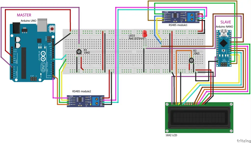
In this article, we shall be connecting two Arduino to an RS485 in order to read the data. To do so, you will first start by making a circuit connection in your first RS485 and your Arduino Uno; this will serve as the Master. Once that is done, you will go ahead and carry out a connection for the second RS485 and your Arduino Nano that will serve as a Slave.
When you are done with that, you will proceed and make a circuit connection between your Arduino Nano and the 16 by 2 LCD screen. Connect the 10K potentiometer to an analog pin A0 of your Arduino Uno to help in offering the analog input. Your LED screen should then be connected to the D10 pin of the Arduino Nano.
Connect the components! 🙂

To program both the Arduino Uno and Nano, you will have to use the Arduino IDE. However, ensure that you select a corresponding port by clicking on tools and then port. Once this is done, you will proceed to choose the corresponding board by clicking tools and then boards.
In the Master section, you will take inputs at the Pin A0, which is the analog input by varying potentiometer, and go ahead and SerialWrite the values to youRS485 via the Hardware Serial port of your Arduino Uno. The Port is (0, 1). In order for you to start serial communication at the Hardware Serial port (0, 1), you will have to key in Serial.begin(9600); command.
Furthermore, in order to read the analog value from pin AO of your Arduino Uno and the store them, you will have to use this vital commands intpotval=analogRead(pushval);
Final Word
With the right command and hardware, connecting your Arduino to RS485 and reading the data is relatively easy. All that is required of you is to follow the tips discussed in this article, and the whole process will become a breeze irrespective of your skill level.
If you are looking to use the RS485 as a transmitter, the DE pin along with the RE pin has to be connected to the 5V while the DI pin should be connected to the TX. By doing so, the data will be sent from the TX pin of your Arduino to the DI pin of the model.
On the other hand, when you want to use the RS485 as a receiver, the DE pin, and RE pin has to be connected to the GND while the RO pin should be connected to RO. The data that will be received by RO pin, which is connected to the RX pin of your Arduino, allowing you to read the RS485 data using Arduino.
As we conclude, we hope that you find this article helpful as you try to read your RS485 data using Arduino.

