- An Electrical Circuit
- What Are the Basic Components of an Electrical Circuit?
- Understanding the “Flow” of Electricity Through a Circuit
- What Are the Different Types of Circuits?
- Closed Circuit Definition
- Open Circuit Definition
- Series Circuit Definition
- Parallel Circuit Definition
- Short Circuit Definition
- Final Thoughts…
You don’t think much about it when you walk into a room and flip the light switch do you? How about using your phone or any electrical device in your house like a washing machine?
Electrical circuits are a part of our everyday surroundings, whether we are simply using them, or figuring out how to repair them.
While repairing a complicated appliance like a washing machine may be above your level of expertise, a DIY light switch fix may be more within your grasp.
However, if you know next to nothing about electrical circuits, then this post is a great introductory resource for anyone.
An Electrical Circuit
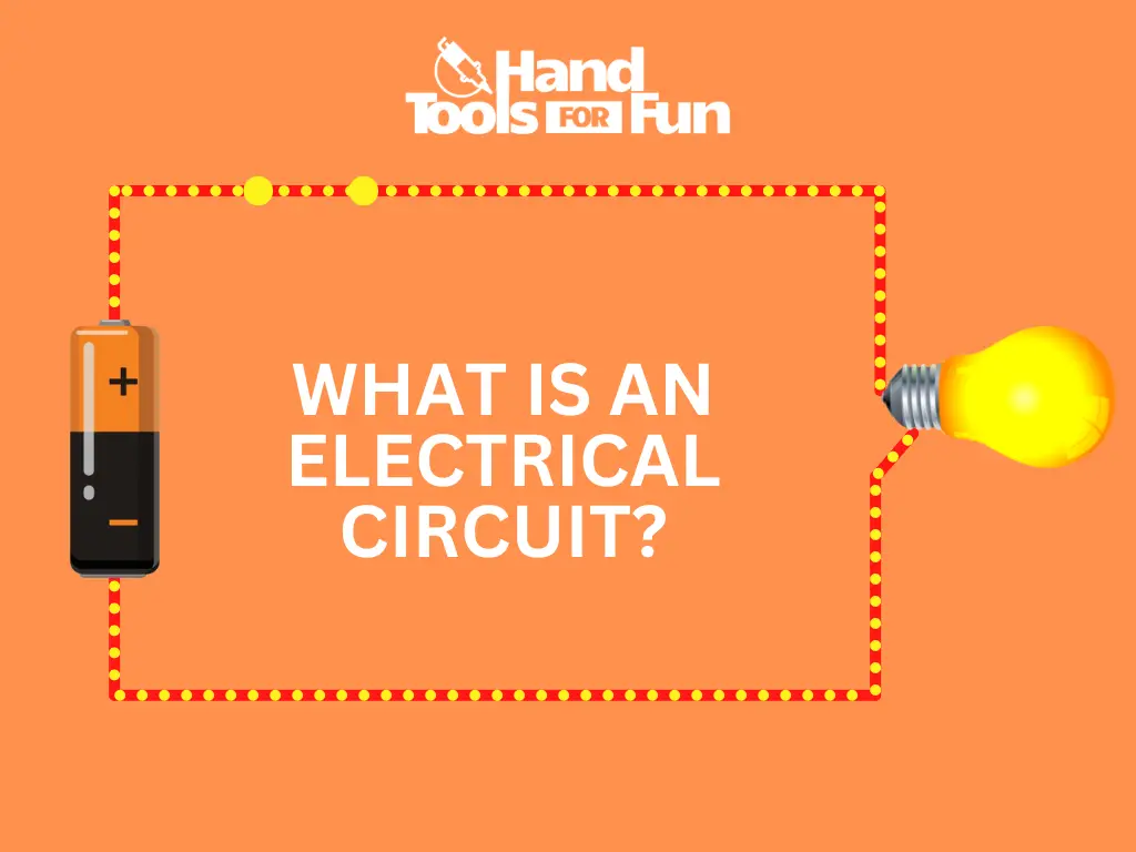
An electrical circuit is a closed, conductive path that causes and facilitates the flow of electrons via a difference in potential, therefore creating an electric current.
In other terms, a voltage source, such as a battery, is connected to one or more components or loads, such as a bulb or a resistor through a conductive material such as a wire in a closed loop. Once the loop is connected, the battery causes current to flow through the completed circuit and make the components work.
What Are the Basic Components of an Electrical Circuit?
Multiple parts go into making a circuit work. There are four basic components that make up and are absolutely essential to an operational electrical circuit.
You have a power source, a material that conducts electricity, a load that consumes that electricity and does work, and a power switch that connects and disconnects the circuit. Here are the four basic components that make up an electrical circuit:
Power Source
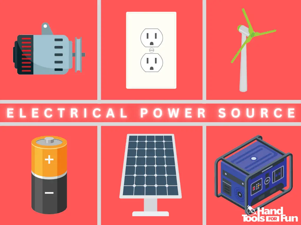
A power source is any device that causes electrons to move along a conductor. This source can come from devices such as batteries, generators, fuel cells, solar cells, alternators etc.
A power source, such as a battery, causes electrons to move by way of a potential difference (voltage), which is the electromotive force that drives the flow of electricity.
Conductive Material
A conductive material is anything that facilitates the flow of electrons. In other words, these are called conductors. Metals, water, ionized gasses, and even living, breathing bodies are all conductors, although some are better than others.
Conversely, you have materials like wood, rubber, the earth, and the air that are considered insulators that mitigate or resist the flow of electricity. A typical electrical circuit utilizes conductors such as wires, cables, or printed circuits.
Load
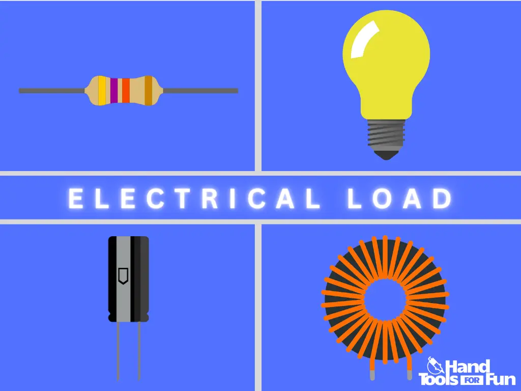
An electrical load is any single component or overall appliance that consumes electrical energy, does work, and produces heat. In a simple circuit you can have loads such as bulbs, resistors, capacitors, inductors, and motors.
More complex devices also consume energy and do work and are also referred to as loads. For example, many household appliances such as washing machines, AC units, and electric stoves are also considered electrical loads.
Switch
A switch is a simple mechanism that sits somewhere on a circuit and its function is to connect or disconnect the overall circuit. Basically, it turns the circuit ON or OFF.
Active and Passive Components
A circuit is made up of active and passive components. Active components are those with the ability to control the flow of electricity. Passive components lack the ability to control current.
Examples of Active components are: Batteries, solar cells, and transistors. Some passive components include resistors, capacitors, and inductors.
Understanding the “Flow” of Electricity Through a Circuit
For an electrical circuit to be functional, three phenomena need to be present. They are: a source of a difference in electrical potential that “pushes” electrons through a circuit, the flow of electrons through a material that presents minimal electrical resistance, and opposition to the flow of electricity somewhere along its path. Here we will learn more about them in detail:
What Is Voltage?
Voltage, also described as potential difference or the electromotive force, is the “push” that causes electrons to move throughout a circuit. Its unit of measurement is called the “volt” named after the Italian physicist Alessandro Volta.
Voltage can be described as “pressure” provided to electrons flowing through a circuit. Devices that provide electrical power such as batteries, solar cells, and generators, produce a power supply that can be measured in volts.
What Is Current?
Electric current is the rate of the flow of electrons or charge past a measurable point in an electrical circuit. Specifically, the movement of one coulomb of charge past a measurable point. Its unit of measurement is the “amp,” or “ampere,” named after French physicist and mathematician, André-Marie Ampère.
What Is Resistance?
Any component along an electrical circuit that reduces or mitigates the flow of current along its path is considered and measured as resistance. Its unit of measurement is the “ohm.”
The ohm is named after German physicist, Georg Simon Ohm. The friction of resistance in a circuit always produces heat.
A resistor is an electrical component that is specifically designed to oppose electric current, although any component or load that consumes electricity has a measurable amount of resistance.
All substances have a certain amount of electrical resistance. Even great conductors such as metal wires aren’t perfect conductors and produce negligible amounts of resistance.
Ohm’s Law
Named after the aforementioned German physicist, Ohm’s Law describes the proportional relationship between voltage, current and resistance. It is represented by the formula, V=IR, where “V” is for voltage, “I” is for current, and “R” is for resistance.
Tweak one value, and another value is affected. For example, increasing resistance decreases current. High voltage and low resistance increases current. Ohm’s law is a fundamental law that governs all electrical circuits.
Which Direction Does Current Flow?
Although the reasoning behind this is beyond the scope of this article, current flow should be understood in two ways: Electron flow, and conventional current flow.
Visualizing current flow from a DC power source, electrons flow constantly from the negative terminal of the voltage source through all the components and loads, before arriving back at the voltage source through the positive terminal. Opposingly, conventional current flows from the positive to the negative terminal.
The Difference Between Alternating(AC) and Direct(DC) Current
Alternating Current is current that changes direction periodically in a circuit. AC produces a wave-like function when plotted on a graph. One side is called “phase,” the other is “neutral.”
Let’s say you have a circuit run by a 12V AC power source. A cycle in that AC circuit will begin at zero, reach a maximum of 12V, fall back to zero, shift and move to the other direction to a maximum of -12V, back to zero, and then start the cycle all over again. When graphing this cycle over time, the resulting graph creates what is called a sine wave.
Alternating current is typically used in transmission lines along the power grid and powers homes and business. In a normal house, the power supply coming out of your electrical receptacle can have 60 of these cycles occurring in one second.
Direct current supplies and maintains a constant current direction throughout the circuit over time. If it were to be plotted on a graph describing its movement over time, then you would see a constant straight line at 12V hovering above zero.
Simple hand-held devices around your house like flashlights, cell phones, and Laptops all utilize a DC power supply. For the examples of simple electrical circuits further down this article, we will be focusing only on examples supplied by Direct Current.
What Does the Term, “Voltage Drop” Mean?
If you can imagine electrons flowing through a circuit as you would water flowing through a pipe, you could also imagine a clog in a pipe as a resistor. A water pump supplies the water pressure(voltage) into the pipes and water rushes against the clog.
In a circuit, electrons collide against the resistor converting the electrical energy and releasing heat. That pressure of voltage is like the water pressure against the clog.
Electrons, like the water against the clog, get bottle-necked against the resistor. As current flows out of the resistor, the voltage or pressure is noticeably less than before the current entered the resistor.
In the water example, water hits the clog at high pressure, but for the water that escapes the clog and makes it through, the pressure of that water has decreased a certain amount.
As the water pressure has dropped, so has the voltage(pressure) in the circuit “dropped.” For each component in a circuit that creates resistance, the voltage drops for each one. The voltage drop across any component in a circuit is proportional to its resistance.
Visualizing the “Flow” of Electricity
We can now put it all together and visualize voltage, current, and resistance. As before in the previous voltage drop example, let’s use the water and pipe example again.

We can imagine a water pump(voltage) applying pressure and forcing water through pipes. The pump pushes the water and causes it to flow at a certain rate through the pipes(current).
Along the way you may have certain obstacles such as a clog or water filter(resistance). When using this analogy to visualize the flow of electricity and its fundamental parts, comprehending the way a circuit works gets a bit easier.
What Are the Different Types of Circuits?
There are five basic types of electric circuits. In this post, we’ll be taking a beginner’s look into what these different types of circuits look like, how they function, and how voltage, current, and resistance are affected by the different configurations. In this article we will examine only DC-powered circuits.
For series and parallel circuits, examples will be given and illustrated in order to help you better grasp the concept. Now let’s dive in and take a look at the five main types of circuits:
Closed Circuit Definition
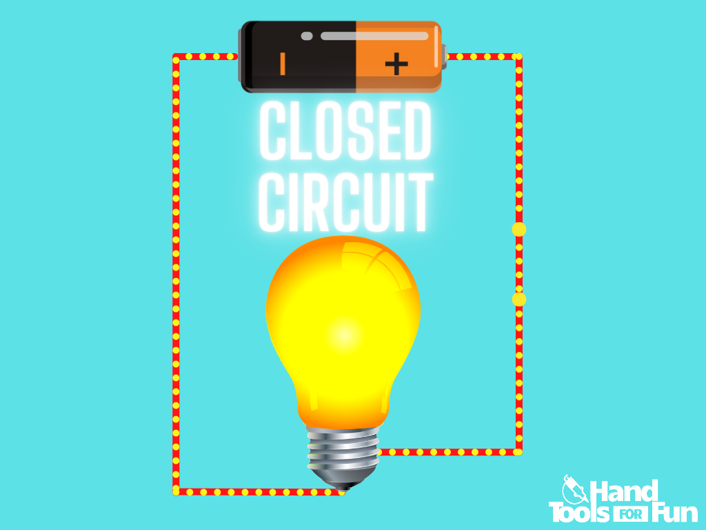
A closed circuit is a closed loop made of a substance with very low resistance or very high conductivity (a conductor) such as a copper wire for example, that has both ends connected by a voltage source. The connection allows a path for electrons to flow from the negative to the positive terminal of the voltage source.
Open Circuit Definition
An open circuit (or open loop) is a situation in which there is a gap or disconnect somewhere in the circuit causing there to be no path for current to flow. This could be caused by an opened switch, a malfunctioning load, a break in the wire, a dead voltage source etc.
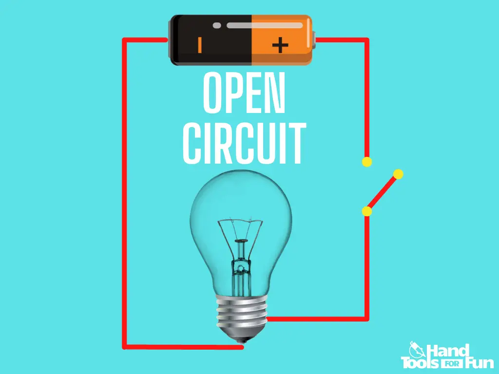
This situation causes a break in the circuit, and thus no path for electrons to flow from the negative terminal of the voltage source, through the entire circuit and through any possible loads, and then back to the positive terminal of the voltage source.
Series Circuit Definition
A series circuit is a circuit in which all loads are in line, or in sequence one after another.
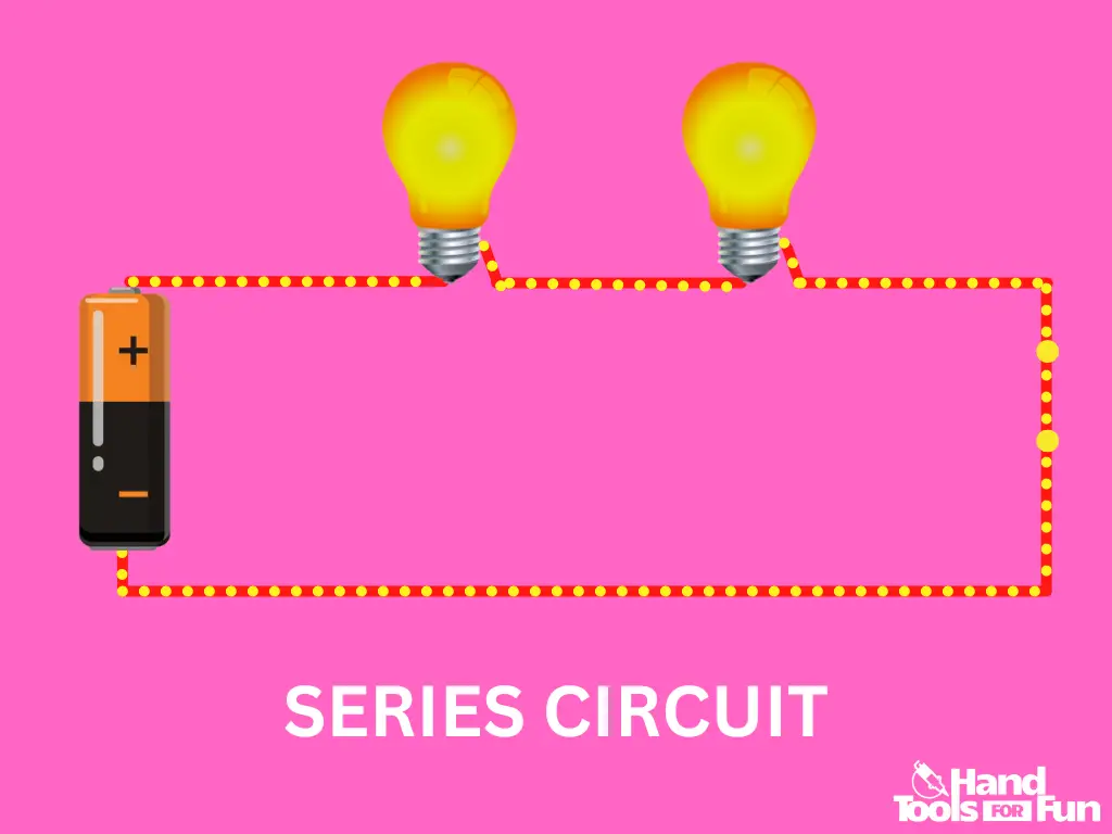
To find the total resistance of a series circuit: Simply calculate the resistance of all the components. Their sum will be the total resistance of the circuit.

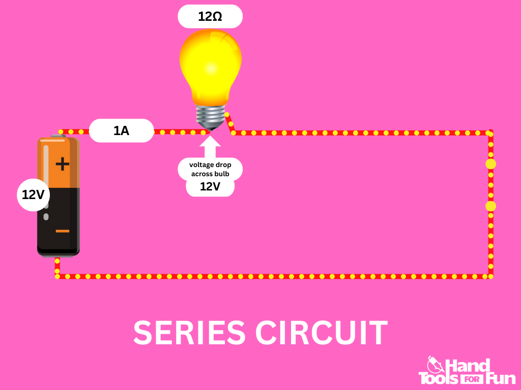
The current remains the same through every component and throughout the entire circuit. The voltage drop measured across each load is a function of the number of loads or resistors in the circuit and their sum will equal the source of the voltage. The voltage drop is equal to its resistance times the current.
For example, If the voltage source is 12V, you have a current of 1A, and you only have one 12Ω light bulb in the circuit, the voltage drop across the bulb will measure 12V and the current through it will measure 1A.
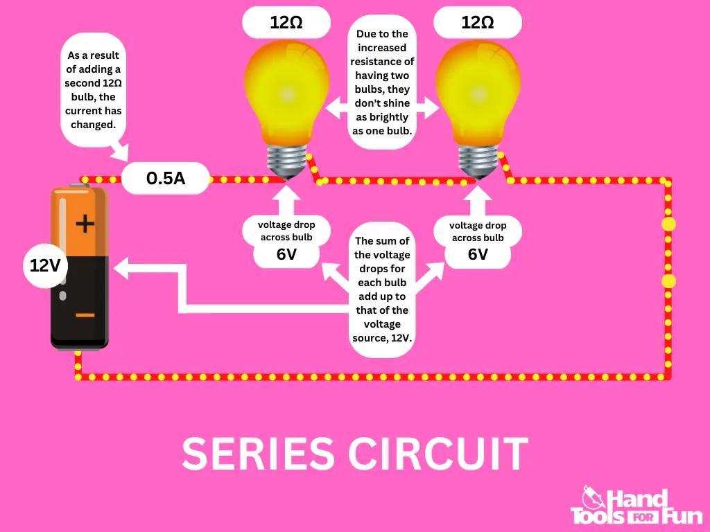
Now let’s add another light bulb in a series. The voltage source is still 12V, but the current is now halved at 0.5A, and you have 2 identical 12Ω light bulbs in a sequence.
The total resistance is now 12Ω + 12Ω = 24Ω and you now have: 12V= 0.5A*24Ω which falls in line with: (V=I*R).
When the voltage is measured across each of the bulbs, the voltage drop across each bulb will measure 6V. The sum of the voltage drop between the two loads will equal the source of the voltage, and the current through each load will measure 0.5A as it is throughout the entire circuit.
What are some examples of reasons for wiring components in a series?
- Powering most simple lighting devices with an on/off switch (flashlight/laser)
- Powering a string of low voltage components with a high voltage source without the use of a transformer
- Handling a high current that is spread across multiple resistors instead of one
What issues can arise when wiring components in a series?
One notable issue of a series circuit is that if one of the components/bulbs/fuses/loads burns out, then the entire circuit is rendered defunct and no current will flow. An example of this would be old fashioned Christmas lights.
Most Christmas lights nowadays are wired in parallel rather than in a series. If one of the bulbs in a series goes out, then the entire string of lights will not function. You’d have to go through and painstakingly test every single bulb until the burnt-out one is discovered.
Another thing worth noting is that the overall current decreases with each added component in a series due to the increased resistance. This also decreases the output of components such as light bulbs as they will begin to shine dimmer with each added bulb.
Parallel Circuit Definition
A parallel circuit is a circuit in which the components are wired and aligned in parallel with one another, rather than in a sequence. In this type of circuit, the path emanating from one terminal of the voltage source branches off into two or more pathways for current to travel along, then recombining back into one pathway before reaching the other terminal of the voltage source.
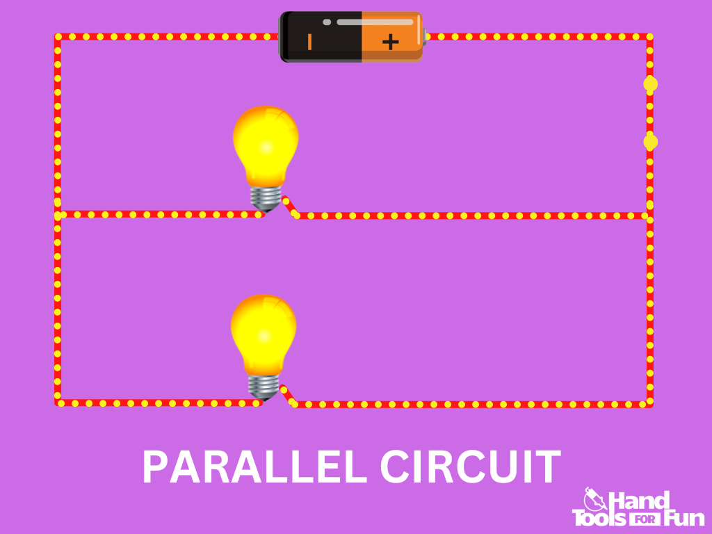
To find the total resistance of a parallel circuit: Divide 1 by the total resistance of the first parallel branch. Repeat this for all parallel branches. Add all resulting fractions together. Divide 1 by their sum.

In a parallel circuit, the voltage drop measured across each branch in the circuit is equal to the voltage source. If there is only one load on a branch, the voltage drop measured across the load will be equal to the total voltage drop across the entire branch, which itself, is equal to the voltage source for the entire circuit.
If there are multiple loads on a branch, then the total voltage drop of that branch will be the sum of the voltage drops across each of the loads. The sum of the voltage drops measured across each load on a branch will still equal that of the voltage source.
The current however, is a function of the number of branches in the circuit, and the current measured around the terminals of the voltage source is the sum of the current measured across each of the branches in the circuit. The more branches are added, the more current is drawn.
For example, let’s go back to the example of the 12V circuit with a current of 1A and only one 12Ω bulb. Now let’s add another bulb, as you may have already guessed, in parallel.
The total resistance is now 1/((1/12Ω)+(1/12Ω)) = 6Ω.
As you can see, the current has now doubled to 2A when measured around the terminals of the voltage source.
However, when the current measurement is taken at the branches and across each of the bulbs, the current measurement is 1A on both branches and through each bulb.
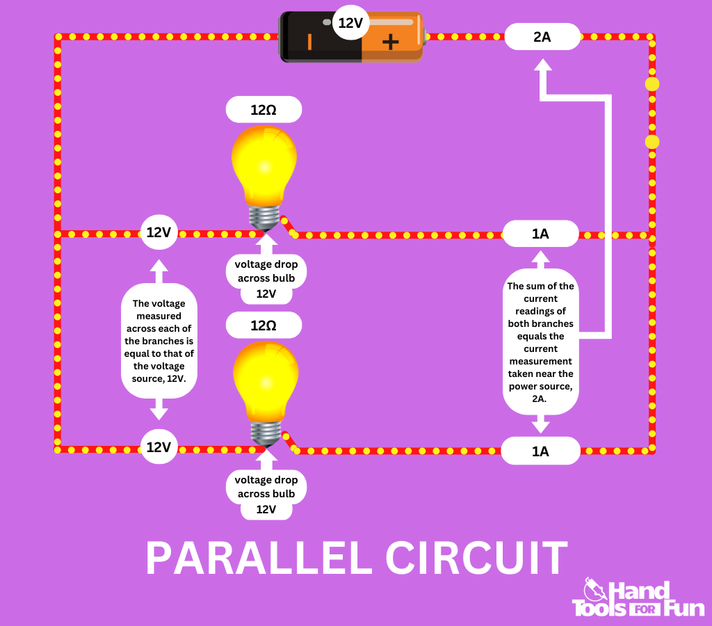
The sum of the current through each branch is equal to the current measured around the terminals of the voltage source. The voltage drop across each bulb is still 12V, which is equal to the total voltage drop across the branch, which itself is equal to the voltage source of 12V.
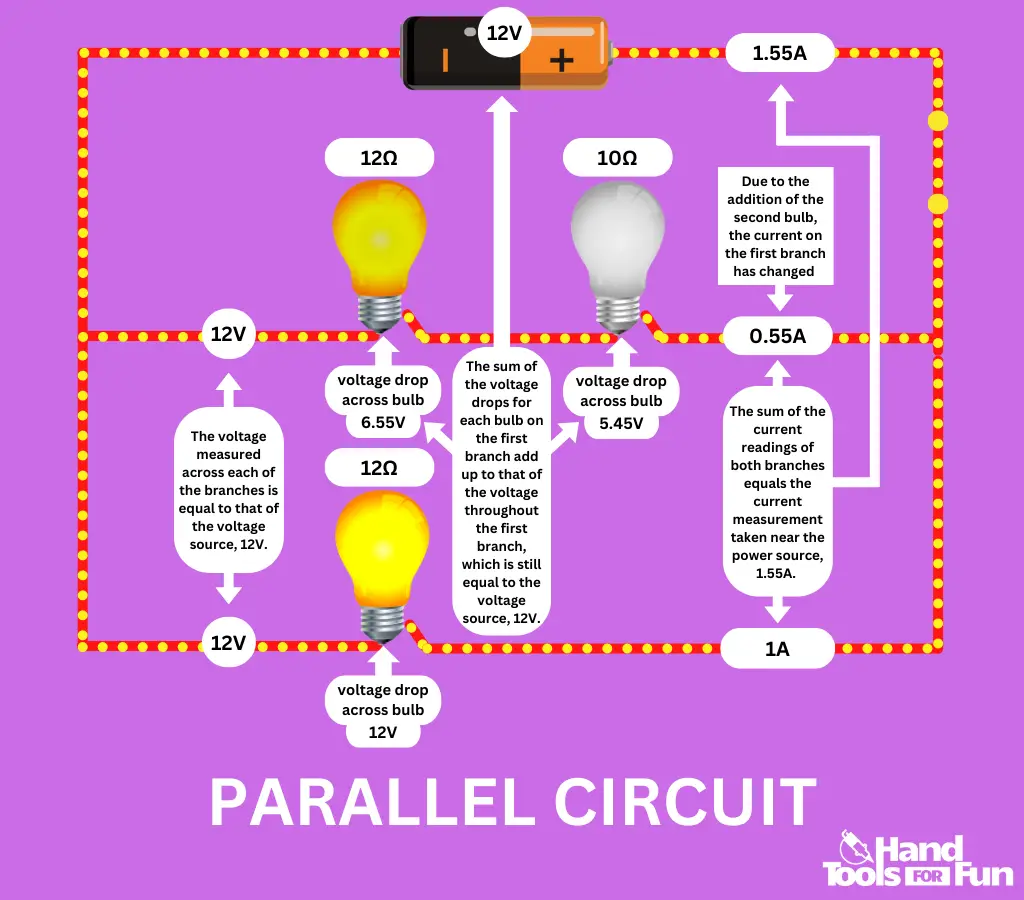
Now let’s make things a bit more interesting. Let’s add another bulb in a series next to the 12Ω bulb in the first branch, but this time it’ll be a 10Ω bulb.
Be careful when measuring the resistance across the first branch; You will use the series formula. Therefore, the resistance across the first branch is now: 12Ω + 10Ω = 22Ω. However, the total resistance of the circuit is now: 1/((1/22Ω)+(1/12Ω)) = ~7.76Ω
Due to Ohm’s law and the relationship between voltage, current, and resistance, the current of the first branch is reduced to 0.55A and therefore the current around the voltage source is now 1.55A when adding the total current measurements of the branches.
When we measure the voltage drop across each bulb on the first branch, the two bulbs in series give different readings, due to the differing resistance measurements. The voltage drop across the 12Ω bulb is 6.55V, and the voltage drop for the 10Ω bulb is 5.45V. If you add these voltage measurements up, you get 12V, which is the total voltage drop of the branch and which is also equal to the voltage source, 12V.
What are some examples of components wired in parallel?
- The electrical grid
- Street lamps
- Christmas lights
- Car headlights
- Home/building wiring
What issues can arise when wiring components in parallel?
Due to the nature of this type of circuit, more complex parallel circuits can be a mess when managing current and resistance.
Also, due to the increased draw from increasing branches, parallel circuits are more demanding and can be energy intensive. An adequate power source needs to be used when powering them.
Short Circuit Definition
A short circuit is a situation in which the positive and negative terminals of a voltage source are joined by a highly conductive material with minimal resistance along the path. As the electric current takes the path of least resistance, this causes maximum current to be drawn from the power source as it flows largely unimpeded throughout the circuit.
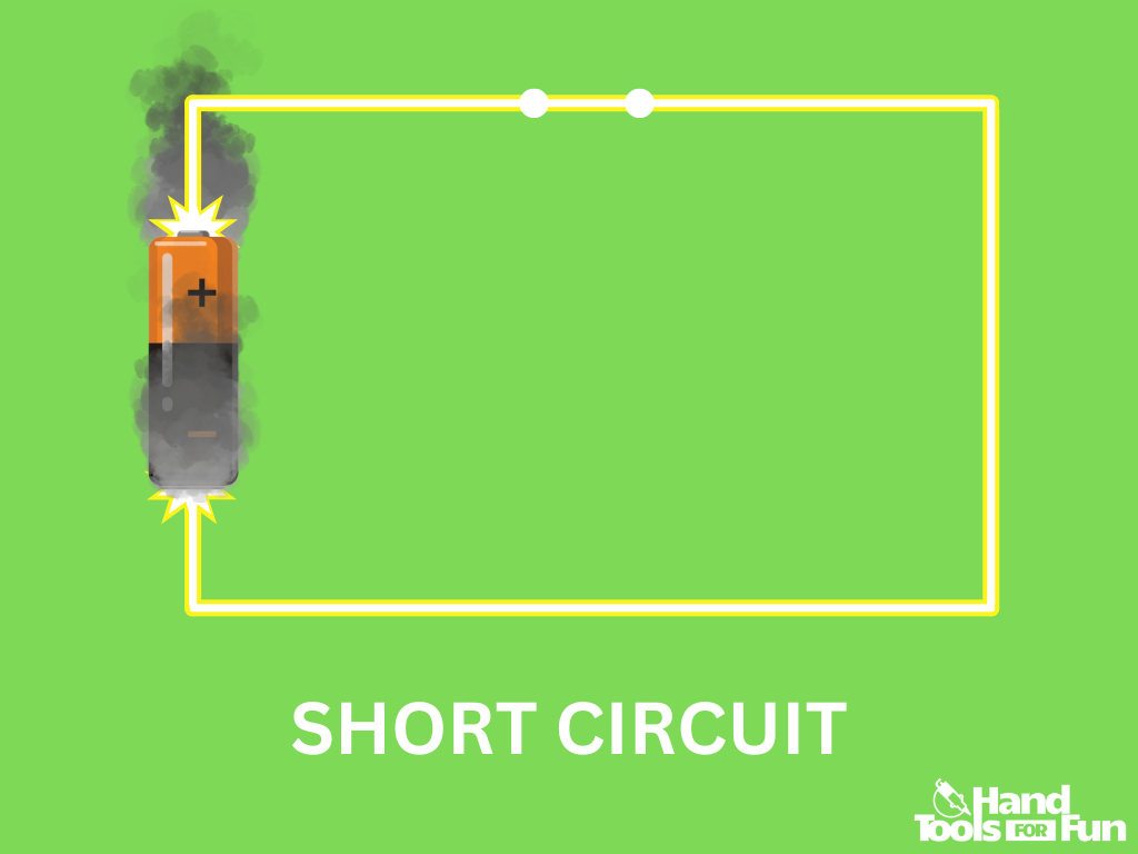
If the wire is too thin or conductive, then it may heat up, and if the components on the wire are not suited to handle very high current, then they may become overloaded, heat up, and melt. The voltage source(a battery) may even begin to burn or even explode.
Let’s look at a normal functioning circuit as an example. In this simple circuit, the battery powers the bulb on the opposite side of the circuit.

Now let’s add a bare parallel branch with no loads in between the battery and the bulb. When the branch is connected, the bulb goes out. You’ve got a short.
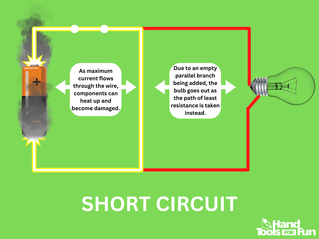
As mentioned before, electricity will take the path with the least amount of resistance. You gave the option of a path with a load in the way, which would result in work to be done in order to pass through it, but you also presented an opportunity for electricity to pass through a pathway with no loads and therefore minimal resistance. With minimal resistance in its way, the short circuit is now free to draw maximum current.
What are some reasons for a short circuit occuring?
- Moisture in an electrical device
- Lack of or inadequate wire insulation
- An increase of current draw beyond capacity due to an increase in power demand
- Building a device with a poor ability to handle the necessary amount of current
What issues can arise when a short circuit occurs?
Any shorted device plugged into a wall may begin to overheat, before ceasing to function. Shorted home circuits are very dangerous. They could potentially cause a fire. They pose a tremendous threat of injury and should always be avoided by taking necessary precautions.
Final Thoughts…
As a DIYer, it’s important to be familiar with some terms as they may come up throughout your time working on various electronics projects. Knowing the five basic circuits is just enough to help you begin to understand what may be going on or going wrong when working on your electronics projects.

