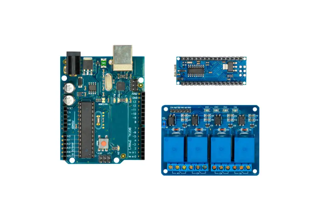
A hobbyist’s mind is always running with ideas, most of which come to fruition as projects, showing off their geeky side. With technology on their side, the tasks can easily come to life and bring about new concepts. Arduino is one of the electronics platforms you can pick as a hobbyist or a tech geek to try new ideas.
Arduino’s platform relies on its easy to use hardware and software, and there are several projects to implement with it. We will look at how to connect a 12V relay board to Arduino, which is a precursor for various propositions, especially if you are into do-it-yourself stuff.
Understanding the Relay
The relay is the electrical switch that completes the circuit, depending on the electromagnetic frequency. It comprises a wire coil and contacts. The relay’s electromagnetic properties allow it to close the circuit when there is electrical current passing and will break the circuit if there is no electricity passing.
Once you understand how the relay works, you can connect it to Arduino when coming up with various devices, especially those concerning home automation.

Step by Step Method of Connecting a 12V Relay Board to Arduino
Here is what you will need to start you off.
- Arduino
- Diode
- A multimeter to measure variables
- Transistor
- A relay with a 12V coil
- Power source
1. Measuring the Coil Resistance
Before making the necessary connections, you need to have an idea of the coil’s current. You can use the multimeter to give you the right measurements. Set the measuring device to the ohmmeter setting and place the two probes on the coil’s pins.
Some relays have the pins labeled, where you look at points 2 and 5 to get them. However, if there are no labels, you have to measure every pin, with your value being between 100 and 10000 ohms, representing the pins’ two terminals.
Through measurement, you can map out the NC (no cut), the C (common), and the NO (no open) poles. Once you measure the resistance, you should calculate the current amount that will flow using the values acquired in measurement. A point to note is that Arduino can handle current up to 30mA. Anything above this value calls for a transistor.
2. Choosing Your Transistor and Diode
The values you get from the firsts step will help you pick the right transistor. The transistor should be of NPN type rather than PNP, and its VCEO rating should be larger than the supply voltage.
The transistor is essential in this setup, playing a role in amplifying and switching electrical signals. Once you have the right resistor, look for a suitable diode to help stabilize the current.
3. Assembly
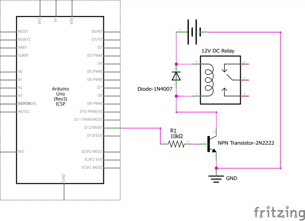
The assembling part is both the most exciting as well as challenging. A schematic diagram can help you out, where you get a clear hint of where each connection goes to.
You can point out the pins on your module, with the NO, C, and NC points being high voltage, bringing in power from the external power source. The low voltage points will connect to Arduino.
Connect the components! 🙂

4. Connecting to The Power Source
The power source connection is vital for your project, especially for troubleshooting purposes. As mentioned, the NO, C, and NC are the high voltage points, and here is where you link to the power source.
It would be best if you understood the pins, with common referring to the common pin. The normally closed pin comes to play when you want the relay to be shut by default. In this case, the current flows unless you initiate a signal for it to break. The normally open pin usually is open until it receives a signal from Arduino to shut it. It works opposite to the normally closed pin.
5. Connecting to Arduino
When connecting to Arduino, you need to know that the GND indicates go to ground, IN1, and IN2 control the first and second relay respectively, and the VCC goes to the 5V. At this point, your hardware part is all set.
6. Creating the Code
The final step is creating a code for the system. to generate the code, you need to use the Arduino language, which is one thing that sets this system apart from others. The language is specific to the Arduino software and boards, based on Wiring.
Copy the code to an Arduino IDE then upload it to the board. If you are knowledgeable with coding, you will understand how to come up with variables and interrupts to make it work.
You can test the system with a lamplight.
Things to Keep in Mind
- Always exercise safety, especially with the connection to the mains, as there is the risk of electrocution and other hazards.
- Setting the relay board yourself is for credibility as a hobbyist; optionally, you can go for a ready set relay module.
- A schematic diagram will help you in many steps, primarily when mapping out the pins and knowing the necessary connections. It is a useful tool for beginners.
Conclusion
If you are a hobbyist, you should try out Arduino as the basis of your next project. It is an excellent open-source electronic platform, providing both hardware and software which improve its overall usability.
The Arduino boards can read inputs from lights, touch, and other stimuli to give out the right output. Above is how to connect a 12V relay board to Arduino, showing you the steps to follow.
It gives you an in-depth look at how to pull such a project from the basics where you unearth its resistance and calculate its current. The Arduino language takes over the coding stage, and it would help if you knew it before picking the project.
Pay attention to safety and see the work come to life.

