The control of high voltage is Arduino’s most adequate functionality; however, as it applies a 5V power supply, its ability to control appliances that require high voltage makes it inadequate.
A relay regulates the flow of current by electronically turning on or off the electromagnetic switch. Therefore, a 5V relay is the most effective alternative to control the (120-240V) current intake.
Programming of the Arduino is required to start-up the relay. The Arduino can be programmed to be triggered by different events that might occur. A sensor or set time intervals switches on or off the 5V relay.
These various events can include temperature (thermistor exceeds 32 degrees Celsius) and resistance (photo-resistor drops below 350) regulations.

How a 5V Relay Works
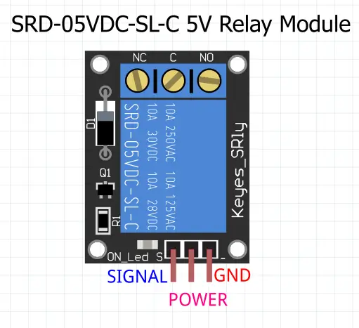
SRD-05VDC-SL-C 5V relay is the most popular relay used in Arduino and hobbyists electronic DIY’s. It has (NC, C, and NO) terminals of high voltage that control the device connected to, while low voltage (Ground, VCC, and Signal) pins to the Arduino. Check the listing below.
- NC- Normally closed terminal
- NO- Normally open terminal.
- C- Common terminal
- Ground- connected to Arduino’s ground pin
- VCC-connected to Arduino’s 5V pin
- Signal- it’s the carrier of the signal trigger that starts the relay from the Arduino.
The relay becomes electromagnetically charged whenever it receives a high signal. The process leads to the electromagnet switching.
Starting up or shutting down the relay depends on the 5V signal. This process is made possible by normal open and normally closed electrical contacts inside the relay.

The relay receives the current from the terminal (C). The terminal (NO) is used for the normal opening of the connection while the terminal (NC) closes the contact.
Relay Pinout
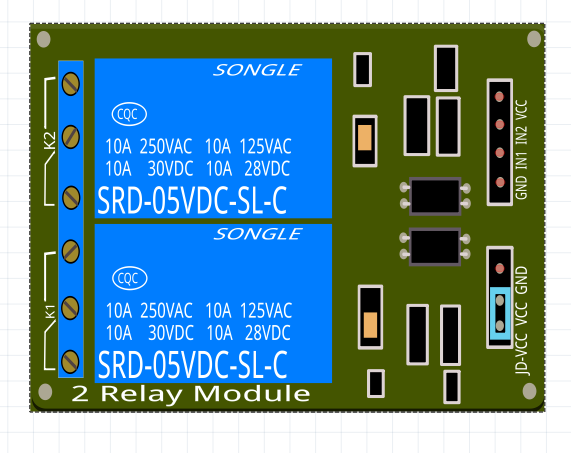
High voltage is connected on the left side by six pins, while low voltage connects to the Arduino pins’ right side.
Mains Voltage Connection
There are two joints on the left side to receive the high voltage, each containing three sockets, which include:
- COM-Common pin
It’s the middle pin of the Arduino relay module.
- Normal open
In this configuration, the 120V-240V closes the switch when a high voltage signal is received, allowing the current to flow from terminal C to terminal NO. The relay’s deactivation occurs when a low signal is received, leading to the current flow being stopped. The relay stays open; hence the circuit is broken until Arduino sends a closing signal.
- Normal close

In this configuration, the switch opens as the signal goes high, leading to the current flow interruption of the 120-240V. Current flows from terminal C to terminal NC when the signal is low, which leads to the switch closing. Consequently, the current is always flowing until a signal is sent from the Arduino to open the circuit, henceforth breaking or stopping current flow.
Pin Wiring
Four pins are located on the right side with low voltage, containing three pins.
A VCC and GND are the first set on the right that powers up the module, and the bottom relay is controlled by input (IN1), and the top relay is controlled by input (IN2). The GND, VCC, and JD-VCC are the second set of pins. The electromagnetic relay is powered directly by the Arduino Board, and in case of a relay problem, the microcontroller might get damaged.
A jumper connects JD-VCC and VCC to verify if the Arduino is physically connected to the circuit or not. The JD-VCC and VCC are connected when the jumper is on, which means that the relay is directly electromagnetically powered from the Arduino’s power pin. The Arduino circuit and the relay module are not isolated physically.
In the case of no jumper cap, the powering up of the electromagnetic relay by the JD-VCC pin, there is a need to provide an independent source of power. This configuration automatically isolates the Arduino and the relay.
The simplicity of the Arduino and the relay connections include:
- GND- connected to ground
- IN1-connected to the Arduino digital pin
- IN2-needed if only you use a second relay to connect to the digital pin of the Arduino
- VCC-connected to 5V
Connect the components! 🙂

Circuit Diagram
The microcontroller connects to the VCC pin to activate the relay via the Optocoupler IC, which connects to the JD-VCC pin that powers the relay’s electromagnet. There is no separation between the microcontroller and the relay.
You can isolate the microcontroller from the relay by removing the jumper connecting to a separate source of power for the electromagnet to the GND and JD-VCC pins. Therefore, the microcontroller is not physically connected to the relay.
Something to be noted is that the input pins are working inversely. The relay is activated when the input pin is low as the current flows from the VCC pin to the ground level input pin. Whereas there will be no current flow when the input pin is high, meaning there will be no relay activation.
Application
Controlling a current load is the relay’s main task; however, Arduino’s operating the relay makes it interesting due to the different applications’ success. Automation of varying area-based programs the system requires different settings depending on the relay load.
You can control a high voltage device by the use of Arduino and any microcontroller. Due to the advanced technology and developing human intelligence, this device can also be controlled by Bluetooth, the internet, emails, remotes, and many more. High or low signals sent through the digital pin of the Arduino controls the output as desired.
Conclusion
When designing a microcontroller circuit, you need to use a translator switch to control high voltage appliances hence, a relay module is essential to regulate the current flow. A relay is electrically operated, and you can integrate with other smart features in various developer’s projects.
In intelligent home automation, try to connect some high voltage devices such as TV, security lights, and air conditioners with a wireless connection like the internet and Bluetooth.


