Making connections is easy…
No matter if you want to meet a new friend or put two devices or different software together, the connection part is easy if you do it right. The hard part is making sure the connection is compatible.
When it is, you get a beautiful relationship and can accomplish many tasks. The hard work goes into making sure there are no weak spots in the connection and that each part has attached to the right counterpart.
To find out how to connect I2c LCD to Arduino systems just continue to read our article. Its short and sweet and gives you the information you need to know about.

5 Easy Steps
The good thing about this project is that it is not complicated or very difficult to get done. You just need a little skill and a little time to make sure you line up the connecting parts and put them together in the right fashion. Here are the easy steps to follow to complete this task:
Step #1: Gather Your Materials
To get started it is best to have everything you need right in front of you or very close at hand. This saves time and lets you get done quicker and be more efficient. The materials you need are:
- 1 Arduino UNO
- 1 16 x 2 LCD display with i2c module
- 1 USB cable
- 4 male to female jumper cables
Once you get these items together you can start your project. Make sure you go slow and work carefully. One mistake will have you start all over again or need more materials
Step #2: Making The Right Connections
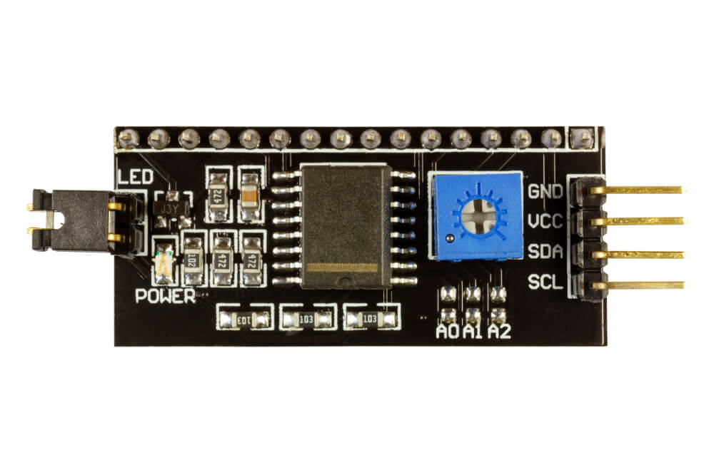
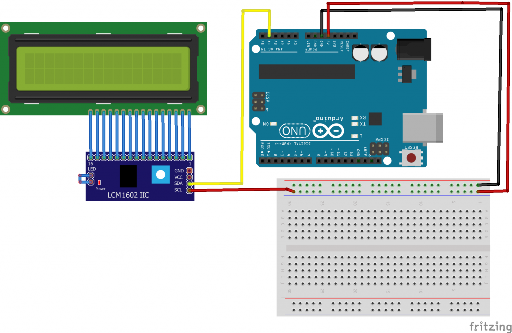
If you follow the upcoming instructions you will notice that this step is very simple. All you have to do is connect the letters to the compatible letters on from one board to the other.
These steps are going from the i2c board to the Arduino board:
- Connect the GND from one board to the GND on the other
- Connect the VCC to the 5V
- Connect the SDA to the A4
- Connect the SCL to the 5V
That should take you less than a minute as both boards are clearly marked. Use a magnifying lens if you cannot see the letters too clearly.
Connect the components! 🙂

Step #3: Installing The Code
Due to certain issues, we can only provide you links to the code and cannot reproduce them here. But this is going to be your most difficult step and getting the code right will make your project.
If you do not get it right, you will break it and have to find the error and start all over again. To see the code in its image format just click here. If that link doesn’t work you can click here to see it.
To make the code work, you need to download two different libraries. The first library is found at this location and the second one is at this location. if either of those two links fail to open you can try this link and see if they work from that web page.
Step #4: The Output Mode
This step is actually taken care of in the above code. Once you get the code installed right the outputs should work like they are supposed to.
Step #5: Watch The Video Tutorial
If you need to see a video or pictures on how the complete process goes together, then you should watch the video at this link. They say a picture is worth 1000 words and when you are connecting electronic devices, that is so true.
Making Those Connections Sure
This is important as loose connections will render your LCD screen useless and waste all that time and effort. If you have never soldered anything before do not fret. The process is simple and anyone can do it.
The first step is to gather your equipment together and we suggest that you use a very thin soldering iron tip as you are going to be connecting wires and circuit boards that come together in tight spots.
The second step is to get your wires in place and make your connections secure. After that, start your pencil soldering iron and let it warm up. Make sure to use the right solder for your connections and there are a lot of them to choose from.
Third, once your soldering iron is ready, apply a little solder to each connection. You do not want too much and have the different circuits touch each other and short the system out so be careful here. Work slowly and just add enough solder to make the connection secure.
Fourth, once you are done, let the solder and soldering cool down. Clean up any mess and clean your soldering iron tip so it will be ready the next time you use it.
How To Connect More Than One Lcd Monitor
This can be done and it will be a bit more complicated than just connecting one LCD monitor to your arduino system. There is a limit as to how many LCD monitors you can connect.
The amount you can connect will depend on how many spare GPIO pins are open for the EN pins to connect to.If you have 5 GPIO pins open, you can connect up to 5 more LCD monitors. If you have 20 open then you can connect up to 20 monitors.
They will all work independently for you. That is a bonus you may not have counted on. To see the schematics on this just click here
Some Final Words
These little projects are actually fun to do. They are quick to do and very easy. Once you master it, you can branch out and add more LCD monitors on your next project. All you need is a little time and to work carefully.
Once you have set those LCD monitors up the next step is to get them to communicate with you with the information you want to read at the time.Let your innovative spirit take over and help you create some wonderful gadgets using the LCD monitor and your arduino uno board.


