
DC motors are convenient, and high efficiency and torque gadgets that make them ideal for robotics. They incorporate two leads, a negative and positive terminal, that will start rotating the motor once connected to the battery directly. On the other hand, the ultrasonic sensor is a gadget which uses sound waves to measure how far an object is positioned.
It achieves this by producing a particular frequency which it sends out and listens as these frequencies bounce back. This allows it to estimate the distance between the object and the sonar sensor.
The delay time between the time of transmitting and receiving the sound is what is factored in when calculating the distance. This formula is:
Distance = (Speed of Sound x Time delay) / 2
The distance is divided by two since it’s sound waves usually travel a round trip, that is, from the sensor to the object and back to the sensor, meaning the actual distance travelled is double.
While making this connection, you also need an L293 motor driver IC that performs like an interface between the robot’s motors and the robot’s microprocessors. The two most popular motor driver ICs are the L293 series like the L293NE and the L293D. Integrated into this motor driver are two H-bridge, the simplest circuit that enables you to control the low current rated motor.
But how do you go about controlling the DC motor using the ultrasonic sensor using arduino? If this is what you’re striving to learn, and this detailed article is the perfect guide on everything you need to know on how to make this operation possible.

Step 1: Assemble The Components Needed
You’ll need several items for this experiment to be a success including:
- LEDs
- Arduino WIFI module
- DC motor
- Jumper wire
- External power supply
- USB cable
- Ultrasonic sensor HC-SR04
- L293 Driver IC
In addition to these components, a laptop is also needed for viewing the Distance on the Serial monitor and uploading code to the Arduino.
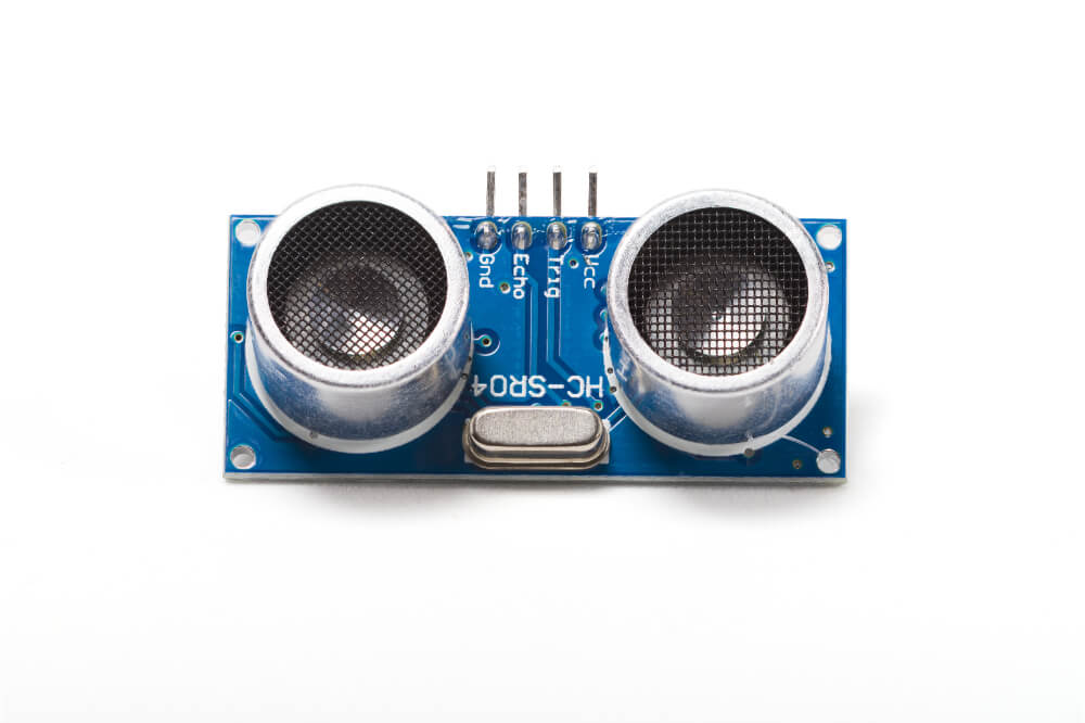
Step 2: Study The Ultraistic HC-SR04 Sensor
The Ultrasonic ranging module has a 2cm to 400cm non-contact measurement functionality that has a ranging accuracy which can reach a maximum of 3mm. Included in all the HC-SR04 modules includes a control circuit, receiver, as well as an ultrasonic transmitter.
The Ultrasonic HC-SR04 sensor has Four Pins, and these are:
- GND (Ground)
- VCC (5V Supply)
- ECHO (Receive)
- TRIG (Trigger)
The main features you should take note of when doing this are:
- A measuring angle of 15 degrees.
- An operating voltage of 5V DC,
- A ranging distance between 2cm to 4m.
- An operating current of 15mA.
Step 3: The Arduino Serial Monitor
Another part of the Arduino IDE is the Serial Monitor which can also be found in Web IDE. With the Serial Monitor, you can send and receive data generated by a board that’s been linked via a USB cable. It does this by observing the Serial Communication concept.
When looking to send commands, all you need to do is keying in into the top of the window and consequently clicking “Send” or “Enter”. After doing this, the data being produced by the board will be shown right below it.
It’s essential to carry out this step when you’re looking to give the board inputs or debugging the code. As a result, it is the Arduino IDE’s most vital tool. The longer you use this tool, the easier time you’ll have when testing complicated projects which offer consequent outputs and take inputs.
Step 4: The Circuit
The HC-SR04 also features four pins that you must follow when making a connection to the Arduino WIFI module including:
- The Ultrasonic Sensor’s VCC pin that’s connected to the Arduino’s 5V.
- The Ultrasonic Sensor’s TRIG pin which is connected to the Arduino’s PIN 9.
- The Ultrasonic Sensor’s GND pin that’s connected to Arduino’s GND.
- The Ultrasonic Sensor’s ECHO pin that’s connected to the Arduino’s PIN 8.
- Connect 2 LEDs that have a 220ohm that are connected to the PIND3 and PIND12 of the Arduino module.
When making these connections, it’s best if you checked the schematics to get a better picture of what needs to be done. Moreover, you need to take into other things when building this circuit including:
- You should also consider connecting the Ultrasonic sensor directly to the Arduino using jumper wires.
- You must never place the sensor on a metal surface to avoid a possible short circuit which might burn and destroy the sensor.
- It’s best to place the electrical tape on the sensor’s backside.
Once you’re done making the connection between the DC motor and I293IC to the Arduino WIFI module, you need to:
- Connect 5V to VSS, Enable 1 as well as Vs on the L293D IC.
- Connect the digital output pins (PIN 10 and 11) on the L293D IC’s input 1 and input 2.
- Connect output 1 and 2 (pin 3 and pin 6) belonging to the L293D IC to the DC motor wires.
- Connect the Arduino’s GND to two of the GND pins located on the exact side of the L293D3 IC.
After making sure all these connections are as required, proceed to add to your board an external power supply.
Connect the components! 🙂

Step 5: Upload the Sketch/ Program
You should upload the program by connecting your Arduino to the computer and proceeding to upload the code. After you’re through uploading the code, the transmission of data to the board will commence. Opening your Serial Monitor at this point will display the distance you’re hoping to measure.
The rotation of the motor that’s connected across the DC motor will be regulated by the input pins (pin 2 and pin 7) for the I293IC. This motor will rotate based on the inputs that are availed across the input pins as HIGH (1) or LOW (0). Once the code has been uploaded, you’ll be able to measure the distance between the object and the sensors.
This result will be displayed on the serial monitor and should proceed to carry out a test on the distance. If this distance is equal or less than 20cm, it means the object is within the range.
Furthermore, the motor and red LED will turn on depending on your logic 1 ( Pin 7 = LOW 0 and Pin 2 = LOW 0). When the distance is over 20cm, the motor will begin with logic 2 ( Pin 2 = HIGH 1 and Pin 7 = LOW 0) while the yellow LED is on.
Conclusion
If you want to know how to control the DC motor using an ultrasonic sensor using Arduino, reading through this guide has offered you useful insights. Therefore, you should follow these steps if you want to conduct such an experiment successfully.
