The rise of LED lights has become popular and easy to control using Arduino. They are inexpensive to develop and use slightly less power compared with other lighting selections.
We’ll cover how to make the most common LED using the Arduino. It’s a simple interactive project, especially if you are new to Arduino programming or DIY electronics.
LEDs are typically controlled using the Arduino IDE. Arduino Uno is a mutual micro-controller used, although any compatible board could be used (like nodeMCU and nano).
It’s a detailed project to guide beginners, and you should learn how to do it because other sensors and modules are programmed using the same approach.
You can apply these lights to make an intelligent LED pixel display or build a personal indoor storm cloud lamp. The circuit requires a 5v vote power to light up. If you need something of higher-tech, then try to make an Arduino lighting system. You can control the brightness of each color of the LED.

Electrical Signals
Arduino communicates with its modules and sensors through switching on and off of electrical current. The concept works exactly like ones and zeros in binary code. The system sends a ‘HIGH’ signal when the current is switched on.
It’s similar to the binary code ‘one.’ A ‘LOW’ signal appears when the current switch off, comparable with zero in binary code. You may adjust the duration in which Current stays on and off from milliseconds up to many minutes.
Controlling the Arduino’s LED
Through Arduino’s serial communication, one of its pins goes HIGH to light up an LED. A low signal is typically sent to one of the pins, and the LED is turned off. To effectively regulate the current flow, resistors of either 100 Ohms or 10k are placed in-line (in series) with LEDs.
The restricted current will keep LEDs safe from blowing off. Brighter lights come in when you use a lower value of the resistor to pass more current flow. The high amount of resistors will restrict the current flow, which makes the LED dimmer.
Lighting up the LED in Arduino
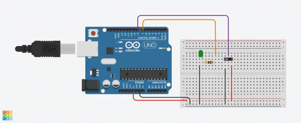
This illustration shows the simplest things you can apply to Arduino to see physical outputs. The set up will teach you how to control LEDs with a switch using the Arduino. Ensure you have the following devices to make the system.
- Jump wires
- 10K resistor
- A breadboard
- An LED
- A switch
- A computer with the Arduino IDE
Powering the Breadboard
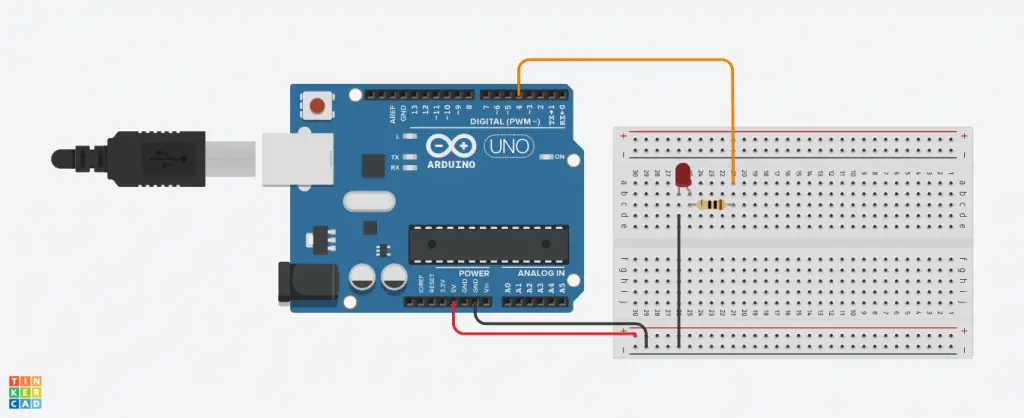
The first step is to attach the 5v power and ground pins. With your jumper wire, insert one end to the Vcc of the Arduino board named ‘5v’ and the other part into the column labeled ‘+’ of the breadboard. Use a red wire for a standard color-coding. Take another wire to connect the GND in the board with the column under ‘- ‘in the breadboard. Again, use a black wire to indicate the polarity.
Attaching the LED
The next step after powering the circuit is now to attach the LEDs. Use a different wire to insert in any digital pin. The other side of the cable should run to the positive breadboard terminal. Use the one end of your resistor to insert into the same row you placed the 5v wire.
It’s essential to integrate the resistor to keep your LED safe from burning. The second end of the resistor is placed on a different row. Finally, take your LED to hook the longer pin in the same alignment with your resistor’s 2nd end. The shorter end is always negative, and you should connect it in the breadboard’s negative column.
Connect the components! 🙂

Setting Up the Arduino Switch
The LED is now well placed in your breadboard, and you have to set the switch. This switch has three pins: the two pins at the end indicate the GND and the Vcc. The middle pin is the data pin and is the one used to record the switch’s state.
Start by placing your switch on the breadboard for the three pins to lie in different rows. Run the wire from the left pin to the breadboard’s negative column and the right-end pin to a positive charge. To complete the switch circuit, connect the middle pin to the selected digital pin of the Arduino. The system is completely set and ready to run the code.
Connect the components! 🙂

Coding Arduino to light the LEDs
Before writing any command lines, always ensure that whatever Arduino board you are using is set under ‘Tools.’ The first step is to declare both switch and LED as variables. For instance, a switch plugged to pin eight can take the variable ‘switch’ and set equal to 8. Similarly, an LED set to digital pin seven can be declared using variable ‘LED’ and set to pin7.
Next, under the ‘setup’ function, make the switch input and the LED as the output using the ‘pinmode ()‘ function. You can choose to start the serial monitor communication though it’s unnecessary for Arduino to light LED. The code under the ‘loop’ function is what runs your program. You can use the if- statement to command your program.
The LED always lights up when the switch is high. use ‘digitalRead (swich)= = HIGH’. The statement will check to see if the switch is HIGH. When its binary code reads one, it proceeds to execute the statement under the ‘if’: ‘digitalWrite (LED, HIGH),‘ to turn on the LED.
When the command line ‘digitalWite(swich) = =High’ is false, it shows that the switch is not HIGH. Execution will continue to the other command-line under ‘else to run ‘digitalWrite (LED, LOW),‘ which will turn the LED off.
Conclusion
LEDs are potent lights used in many different Arduino applications. This project is a simple way to get started, and the idea covered in it can be expanded to make efficient lighting.
With just a few components, you can advance the project to control all your home lights using a smart device. If you got an Arduino starter kit, you could use any sensor to trigger your LEDs when a certain threshold is met.


