When you do not have many tools…
You can create your own. That is one thing this technological age has done for people. It has allowed you to create your own tools, like a voltmeter, and present you with more information you need without using those correct tools.
If you are technologically minded, this gives you an advantage of others when your volt meter breaks down. Just hook up your arduino system and go to work. To find out how to create your own voltmeter through your arduino system, just continue to read our article. It has all the instructions you need.
Materials Required To Complete This Project
There is a long list of materials and supplies and it may take a little bit to compile them all. But once you have completed this project it will have been worth it all. Here is a list of supplies:
- Arduino UNO board —-> Atmega328P datasheet
- 16×2 LCD screen
- 10k Ohms variable resistor (potentiometer)
- 4 x 220k resistor
- 120k resistor
- 1k ohm
- 100nF ceramic capacitor
- 1N4733A 5.1V Zener diode (or equivalent)
- 1N4007 diode (or equivalent)
- Breadboard
- Jumper wires
How To Read Volts With Arduino
Of course, you have to put the device together before you can read it and any instructions to do just that are as follows.

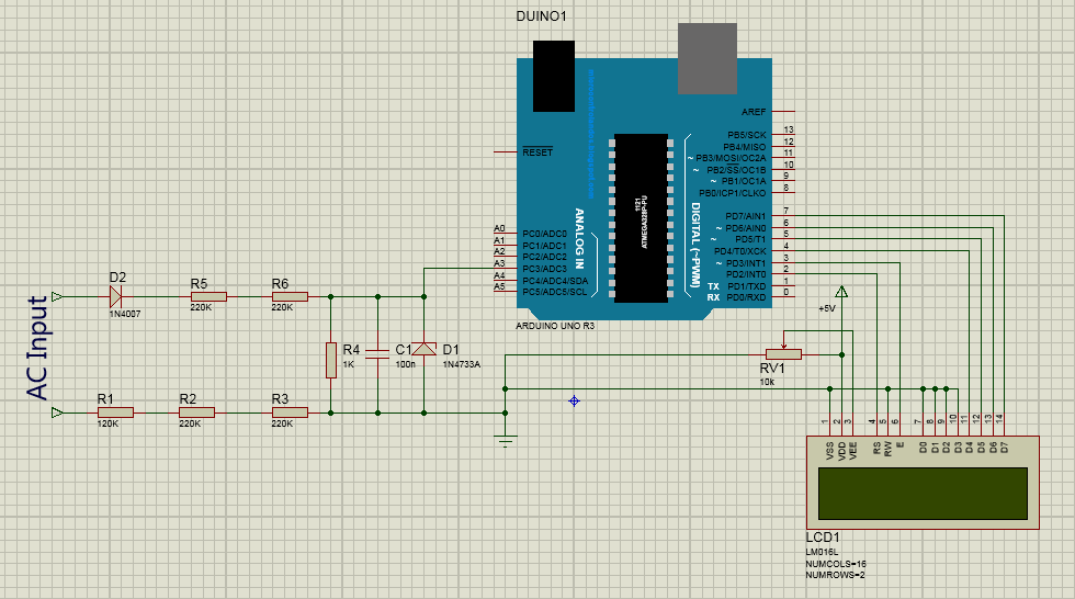
- The incoming AC is connected to a diode 1N4007 which helps negate negative half cycles
- The arduino system cannot register readings above 5 V so a volt division is needed to make this system work. A division is made up of 4 x 220k o resist, 1x 120k resistor and one x 1k resist giving you about one mega ohm
- The arduino system reads The voltage across your divide and divides reading by 1001k
- The 100nF ceramic capacitor stabilizes and eliminates any voltage noise, while 1N4733A Zener diode protects your arduino system from 5.1 or higher voltage

Making All Right Connections
The following table makes sure you know which wire goes to which connection.
| Number | From 16 x 2 LCD screen to | The arduino system |
|---|---|---|
| One | From RS pin to | Pin #2 |
| Two | From E pin to | Pin #3 |
| Three | From the D4 pin to | Pin #4 |
| Four | From D5 pin to | Pin #5 |
| Five | From D6 pin to | Pin #6 |
| Six | From D7 pin to | Pin #7 |
| Seven | VSS, RW, D0, D1, D2, D3 and K to | GND |
| Eight | VEE to 10k o variable resistance output | |
| Nine | VEE pin is used to control contrast of LCD |
There Will Be Code To Install
This code will measure the RMS value of Sinput AC voltager when it detects the value of half wave. It then divides that half-wave by the square root of 2. The equation for this operation is So: Vrms = Vmax/√2.
Unfortunately, even with code, the arduino system will not provide a full accurate reading of active current voltage. It will only give proper reading for the AC voltage input.
To see code that you need to install, just click here and scroll down. code lines go from one to 52 and you will need to scroll down a bit on code to see entire instructions.
If You Want To Read 220 Or 230 Volts
The arduino system is actually quite limited as a voltmeter. It can only read 5 Volts at best. If you want to read on a 220 or 230 scale, you will have to use a step down transformer that can go from 230 to 12 Volts.
Then instead of a capacitor you should hook up a rectifier bridge and a voltage divider. A capacitor is okay for some projects but for others it removes The half cycles which are a needed piece of information for those other projects.
Be careful of just any transformer you use as cheaper models may not produce S waves as they actually should look. Once you are set up that system should be able to read volts using this equation Vgrid=(max/0.230+1.4)*transformer ratio*0.707.
The properties for equation go like this:
- Max= maximum value read by arduino system
- 0.230 = The voltage divider ration
- 1.4= voltage drop on two diodes for half cycle on rectifier bridge
- max/0.230+1.4) = volts before bridge
- Transformer ration = 241.2 volts on primary & 13.48 volts on secondary which translates into a 17.89 ratio
There Is A Simpler Method To Use
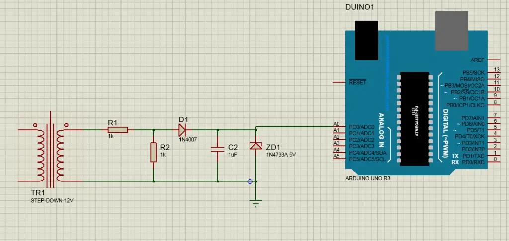
All materials you will need are a Step-down Transformer (12V or 6V),Resistor (2P-1,000 ohm), Diode(1N4007), Zener Diode (5V), Capacitor (1uF preferably), Arduino UNO, and some jumpers(2)

Just connect step-down transformer to arduino system using a divider of voltage that connects with 2- 1000 resistors. Then to get DC reading connect a diode as a half-wave rectifier.
To stabilize the system you need to connect a capacitor to stabilize volts and a zener diode to be used as a volt regulator. Then put jumpers to A0 analog pin on arduino system to its GND.
Then to install code, click here.
Some Final Words
If you find yourself without a voltmeter don’t fret. You can always build your own using your arduino system and a few parts. Being handy is not limited to fixing cars or houses. It works well in electronics as well.
That is a good thing when you find yourself short of those right tools to get your projects completed on time. There is always more than one way to read voltage. You just have to make sure you think outside the box sometimes and make do with the equipment you have on hand.
Then you can do just about anything and get proper readings every time .


