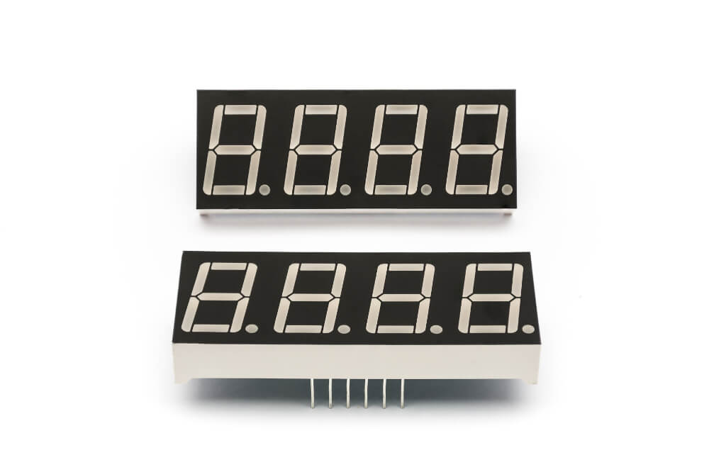
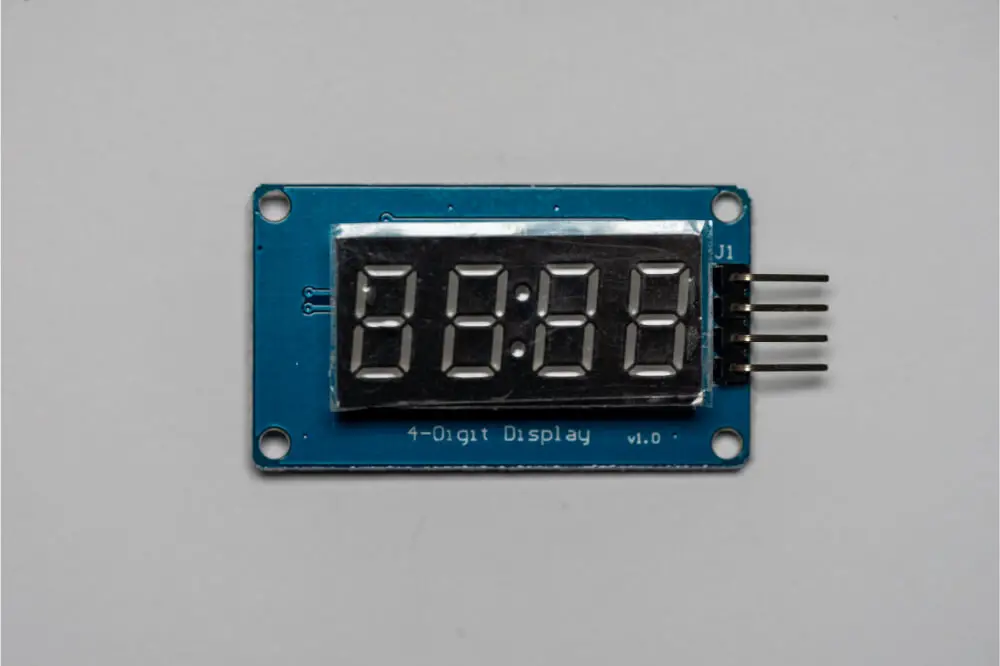
A 7-segment display is an Arduino component for electronic display used to visualize decimal numerals, which are an alternative to the more complex presentations.
It’s made up of seven LEDs (hence its name), which has a rectangular arrangement. Each of the seven indicators is referred to as a segment. This is due to its ability to take part in the numerical digit to be displayed.
Seven Segment Display is widely applied in digital clocks, smart electric meters, and other intelligent devices with a numerical information display. You will also find this display in other household appliances such as washing machines, auto air conditioning systems, and microwave ovens. Many embedded systems and other industrial applications use seven-segment display technology to show their output information.
It’s an efficient and simple way to display numerical information extracted from actuators, sensors, and other quantities. It’s not useful for many applications to integrate a more expensive liquid crystal display to output information. It’s sufficient to apply a seven-segment display.
Use the display technology where your Arduino circuit design requires to display numbers. The seven LEDs in the display are arranged to form a number eight shape. You can efficiently operate the device, and its cost is affordable. In this guide, we will discuss how to use seven segment displays in Arduino.

How 7-Segment Displays Work
Developers choose to integrate the display technology with electronic devices to output decimal numerals ranging from 0 to 9 and, to special cases, basic characters. Seven segments display comprise of LEDs.
They usually glow when they are forward biased. The forward current is the critical determinant of the intensity of the lighting diode. You need to pass sufficient forward current for the display to glow with full intensity.
Common Cathode Vs. Common Anode
You will find two types of 7 segment displays: a common Cathode and a Common Anode. The internal structure of both is nearly the same. The only underlying difference is the standard terminals’ LEDs polarity. For a common cathode, all of its LEDs’ negative charges are connected. The typical anode has all 7 segment LEDs anodes aligned together.
For the cathode display, all the connections of the LED segments align together to GND. You should apply logic 1(HIGH) signal to the individual anode to illuminate every segment. In the common anode, LED connections to join together to logic 1. To illuminate the respective segment, apply ground, LOW, Logic 0 signal to the cathode of a particular element.
Wiring- A connection of 7 segment Display with Arduino
Now that you understand the 7-segment display let’s begin to wire it up with Arduino.
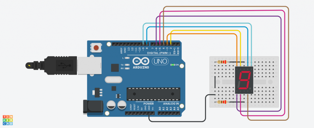
Start by placing your seven segment display device on to the breadboard. Ensure that each side of the display lies on a separate side of your breadboard. As the decimal points face downwards, the pins range from 1 to 5 on the bottom side, starting from left to right. For the upper side, your pins are 10-6 from left to right.
Let us observe the following wiring connection description to understand how to use a seven-segment display on Arduino. Hardware components you need:
- Arduino Uno
- Seven segment display
- Resistors (two 220 ohm)
- Jumper wires
Wiring connection of the pins:
- Pin 2 of the Arduino to pin 9 of the 7-segment display
- Pin 3 of the Arduino to pin 10 of the 7-segment display
- Pin 4 of the Arduino to pin 4 of the 7-segment display
- Pin 5 of the Arduino to pin 2 of the 7-segment display
- Pin 6 of the Arduino to pin 1 of the 7-segment display
- Pin 8 of the Arduino to pin 7 of the 7-segment display
- Pin 9 of the Arduino to pin 6 of the 7-segment display
- Connect Arduino GND to both pin three and pin 8 of the seven-segment display connected with 220ohm resistors.
Note: while your display may work in the absence of the current limiting resistors, always ensure you have them in your circuit to keep your display free from burning.
Once your wiring is correctly done, your circuit should be something similar to the illustration below.
Connect the components! 🙂

Arduino Code
Now, you are about to light up your display with some codes.
If you need to start writing code for your output display, you will first have SevSeg Arduino Library. You can find the Library on the Arduino official website or visit GitHub to find its respiratory and start a manual download.
Install it by opening the Arduino IDE, find sketch>include Library> Add, and then select your library file. You can now write your code and test various displays for your output.
Make sure every command line is a sketch of the display. If your code is well-executed, upload it to the circuit board containing the 7-segment for you to see how it works with Arduino. Try to adjust your code and observe how the display changes.
Examples of how to use 7-Segment Display on Arduino
Many applications use the device together with Arduino to display output data. The process is efficient, and as a hobbyist or a hardware developer, you can invent from the following.
Count Up Timer: it’s a simple program to continuously count from zero to nine and then loop back to the start. It’s the implementation with Arduino can apply to design a smart counting system to monitor parks and stadium entrances.
Displaying sensor data. The 7-segment display can use Arduino to show your sensor data. Sensors like temperature detectors and motion sensors may use the display technology to return information. If you want to modify the readings from other smart systems using sensors, you can follow the concept.
Conclusion
Most digital devices are integrated with a 7-segment display to convert the digital signals into a form that the user can see and understand. The information recorded is numerical data displayed as numbers, symbols, and some primary characters.
The common cathode and the common anode of the segments illuminate to produce a value once a signal is received from the Arduino microcontroller. Electronic hobbyists and developers use seven segment displays to draw information from their Arduino smart systems.

