
The fluorescent bulb will produce little, or totally, no light for it to be pronounced dead, what is irritation to the eyes is the dancing of the light it provides. It will be time for it to be replaced. However, before you go out to look for its replacement, there is a test you should conduct to conclude that it the faulty bulb.
A fluorescent bulb applies fluorescence to illuminate visible light. In its tube is mercury gas that is low in weight. The gas is energized by electric current electrons to produce ultraviolet radiation in the process of discharging the electrons. The coating in the inner layer of the tube is made of phosphor.
- Using a digital multimeter to test the bulb
- 1. Confirm that its not the circuit breaker that has tripped
- 2. Visually inspect
- 3. Check if the connecting pins are broken or bent
- 4. Check if the bulb is working in another lamp
- 5. Scrub the rust and the dust at the holders
- 6. Set your multimeter to test the resistance between the two pins
- Take note of the readings on the multimeter's screen
- Voltage test
- Conclusion
The phosphor coating is what will illuminate light when the ultraviolet radiation is caused. The electric current gets into the tube through the connecting pin, then to the glass stem, and finally to the electrode coil. The tube’s proficiency great energy deal makes it a better option over the incandescent bulbs.
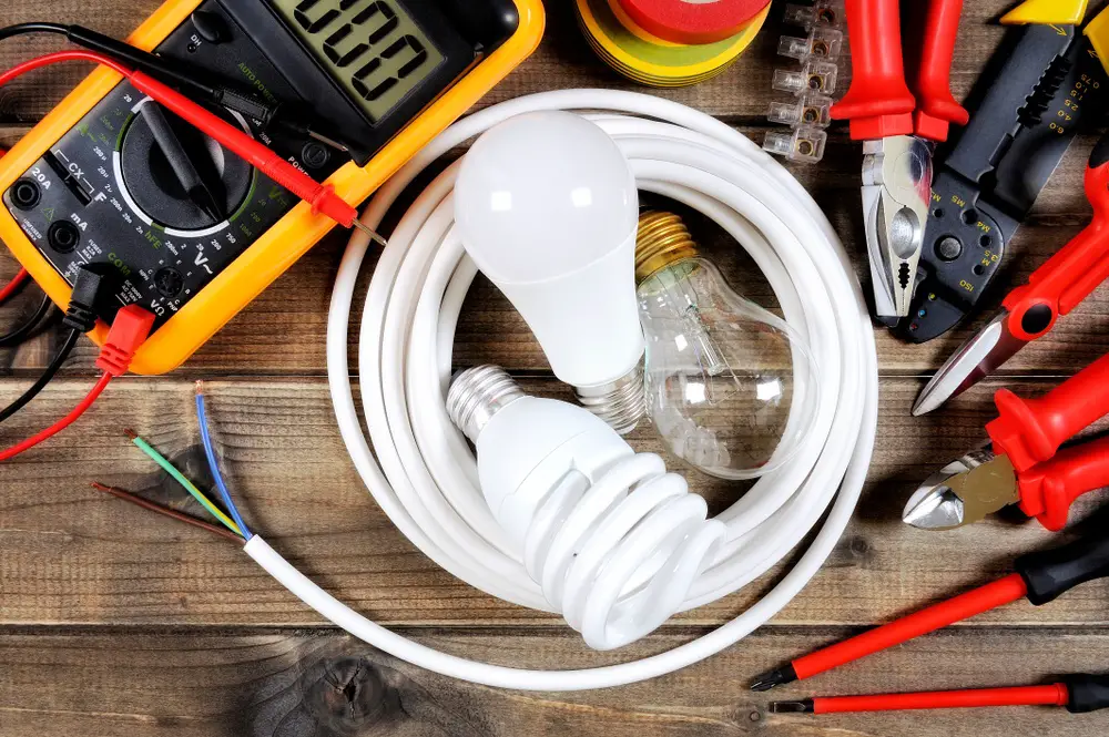
Using a digital multimeter to test the bulb
A digital multimeter is an electronic device that displays its measurements readings on LCD or LED screen. They are highly preferable over the analog multimeter due to their high accuracy, high digital resistance, and the fact that they are easy to read. They are used to measure electric quantities such as resistance, voltage, and current. The following article will guide you on how to conduct tests on a fluorescent bulb using a digital multimeter.
1. Confirm that its not the circuit breaker that has tripped
The circuit breaker is a safety component that breaks the circuit in case of an overload or overcharge from the source. You should check if the circuit is broken. The bulb will completely not emit any light if the circuit breaker has tripped.
Inspect for dark surfaces at the ends of the tube
2. Visually inspect
Using your bare eyes look for the darkish color at the edges of the tube. If they are present, the tube life span is reduced. More electrodes are discharged in the part where the filament is and hence depreciates faster than the regions further from the filament. This is what causes the soot on the outer side of the tube.
3. Check if the connecting pins are broken or bent
The pins are meant to connect the bulb to the lamp, and if they are broken, then no current will flow to the tube. In case they are bent, you will have difficulties fixing the tube back to its position. Using a nose prier, you can straighten the pin that they stand perpendicular to the end surface of the tube.
4. Check if the bulb is working in another lamp
Test the bulb in another lamp. Confirm the testing lamp is functioning. In case it works smoothly, the previous lamp is faulty. The starter could be a problem or a transformer.
5. Scrub the rust and the dust at the holders
The connecting pin may rust due to the moisture that comes in to contact with the copper coating. Rust can be eliminated by scrubbing off it using a scrubbing wire. Also, you can twist the bulb in its holder to eliminate the dust particles that stick in the holder. This should be done when the switch is off. If the lamp is of a double tube, both tubes should install when conducting this test.
6. Set your multimeter to test the resistance between the two pins
Conduct a resistance test of the two pins using a digital multimeter. Below is how to set a digital multimeter to test for resistance,
- Set your digital multimeter to measure resistance. Ω is a visible sign on the multimeter where the dial should be.
- Select the highest possible range of the multimeter
- Connect the black (negative) lead to the common socket (COM).
- Insert the positive lead in the voltage socket labeled (VΩ). After you are finished, you can turn on the multimeter and check if it is working by connecting the black and the red probes. The reading on the screen should be than 0.5Ω for a proper functioning multimeter.
Having confirmed that, you can now go ahead and test the resistance between the two pins on both sides of the tubes by attaching the red and the black probes to the pins of the fluorescent tube.
Take note of the readings on the multimeter’s screen
The reading should be close to zero for a functioning electrode. Any resistance recorded will indicate an open circuit. Could be the filament is blown, and the bulb needs replacement.
Voltage test
After testing the resistance of the fluorescent tube. The next thing to check is the amount of voltage running in the circuit when the system is on. Set the multimeter to measure volts by turning the knob to the alternating voltage mark. It’s denoted by V~. The rest of the setting should remain the same. Below is a procedure that will guide you,
- Complete the circuits using flying leads, i.e., both female ports on the socket on the lamp should be connected to the males on the fluorescent tube by the fly leads.
- Attach one of the multimeter’s probes on one flying lead and the other probe on the next lead.
- Note the reading on the screen.
- With the power on and the intact probes note the reading on the screen
The fluorescent tube is okay if there is a voltage that should indicate voltage specified on the lamp’s transformer. If no voltage is recorded, then the tube is faulty. The test also confirms the continuity is not working.
Conclusion
When conducting a voltage test, confirm the voltage running in the circuit is not too high to blow the multimeter. You should also note that the probes are correctly connected to their sockets. Any faulty recoded when testing electrical appliances should be considered to avoid more damages that could be caused by the faults. Safety is something that should be highly considered when conducting such a test to avoid electrification.
