
Are you a big fan of computers? Have you ever wanted to know more about how to fix your own PC or of those of your friends and family? Does your personal computer or laptop keep on lagging, and you just don’t know what to do to keep it from being that way?
Learning about checking your RAM slot may just prove to be very helpful to you if you want to know how to fix it yourself. If you want to check for the steps and How To’s to test the RAM slot of your computer using a multimeter, then you’re just in the right place! Make sure to list down the important steps below and be careful in checking it without the aid of a professional.
What is RAM?
Random Access Memory or RAM is the memory of the system of your personal computer that helps it Read and Write Data at the same speed that is used in storing working data and machine code. It is found in the motherboard together with all the other components. More RAM means your computer can work with more information at the same time, but having this may prove to have some problems in the future if not properly checked all the time.
What can the multimeter do to the RAM?
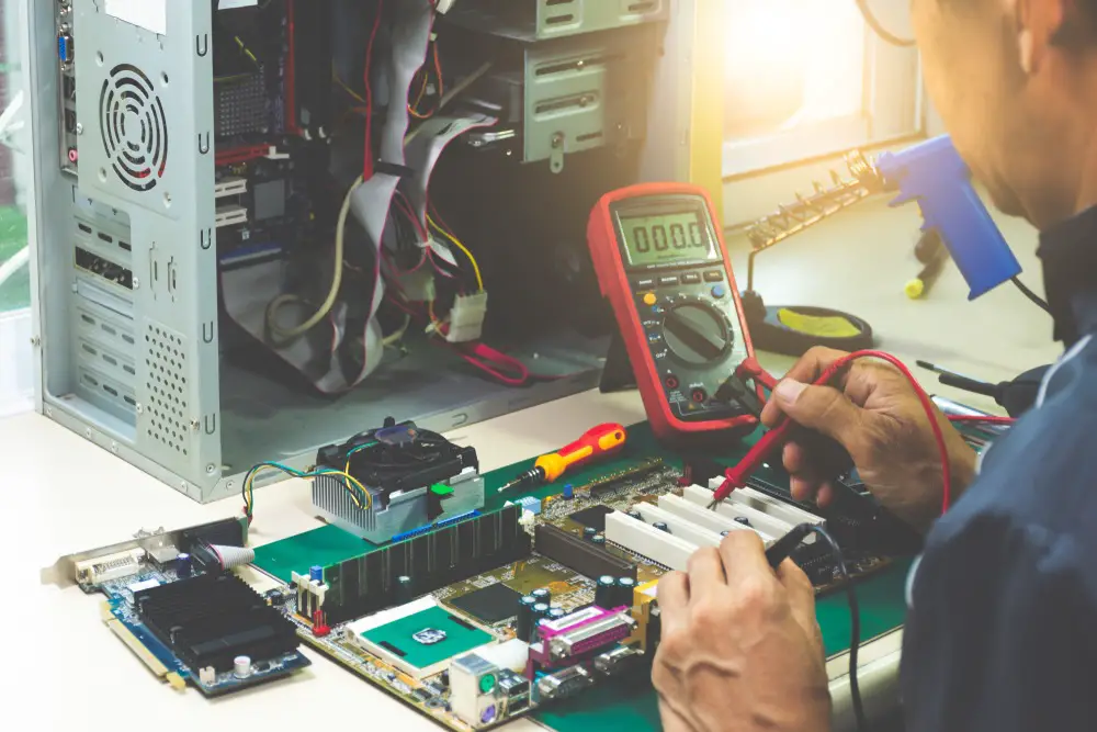
The motherboard of a computer contains various complex circuitry that can be very confusing to anyone who is not familiar with computers and is not an IT expert or professional. By allowing one’s self to use a multimeter, especially a digital one, will make it easier for him or her to check whether its circuits are having any problems or to determine the general electronic troubles that your computer or laptop is currently experiencing.
Steps in checking the RAM with a multimeter:
1. Test the DC voltages
- Look at the 20-pin ATX connector (the main power connector that sends electricity to the motherboard) and make sure that it is properly in. Hook up your personal computer to AC power and then correctly set your multimeter to 20V (voltage) DC. Carefully probe the backside of the connector of your multimeter by using the black probe and setting it in. This should be in contact with pins 15,16 or 17, containing zero voltage, otherwise known as the GND.
- The red probe, on the other hand, should probe to the following indicated pins: Pin 9, wherein it should be violet and VSB, at 5 voltages; while, Pin 14, wherein it should be green and PS On, at between 3 and 5 voltages. After doing so, you can now turn your computer’s switch to power on. Make sure to look if the PS On drops to 0 and if it doesn’t then it only means that you have with you a faulty switch.
- Next up, check the Pin 8, wherein it should be gray and Power_OK, at above 2.5 voltages by simply using the red probe again. Start your computer and pressing the reset button should make Power OK to drop at 0 and then finally back up again.
2. Test the PSU and your motherboard
- Take the plug out of your personal computer and let its remaining power or charge to drain out for a few minutes. Next is to set your multimeter back to its lowest Ohm, which is somewhere around 200 and after doing so, connect the two leads of the probes with each other to cancel out or make the meter zero again. Try touching these leads to the bare metal of your personal computer’s chassis and make sure that the zero reading between the two is the same.
- The ATX connector (the main power connector that sends electricity to the motherboard) should now be properly removed. Use the red probe of the multimeter to carefully check the Power Supply Unit’s (PSU) A/C ground pin while the black wire pin is at the D/C connector. Keep in mind that the black probe at this time is still on the bare metal of the chassis. All readings should be at zero.
- Use the red probe again by checking the colored wire pins’ values that are on the D/C connector or plug. The black probe at this point should still be at the chassis. Readings of the said colored wire pins should now indicate 50 or more.
- The final step! Make sure to remove your CPU from the socket of your motherboard and then finally use the ATX 20-pin chart to help you find the corresponding pin numbers on your motherboard’s connector. The red probe should be used to check the GND pins on Pins 3, 5, 7, 13, 15, 16, and 17, which should all indicate a reading of 0. The black probe should still be at the chassis of the motherboard. Any other reading means that your RAM slot or connector is showing faulty signs.
Now, that you are able to learn of the steps in checking your RAM using a multimeter, preferably a digital one, you are one step closer in understanding the complexity there is within a computer’s system. If all these steps might still be a little too confusing for you, there is no harm in consulting a professional and asking for his/her help. If you find it too expensive to let them handle this job, try and gain more knowledge about RAMs and multimeters yourself, and review the steps above. If not, well, you might just make things worse than it already is.
Lastly…
Periodically, checking the state of your RAM slot and motherboard will help you in determining if your personal computer is having any problems. The sooner you find about them, the better it is for you so that you can quickly take care of it in no time. Kids are not advised to do this at home without a guardian or trained professional.
