
A DC motor in an Arduino kit is by far the most basic of electric motors, and it is often used in several types of DIY projects. Whenever you pass current through the motor, it spins continuously in a single direction until you stop the current. However, you can swap two wires over in order to reverse the direction of your motor.
Running a motor using an Arduino board is pretty much a fun activity that can be performed easily. As a result, in this tutorial, we shall be discussing how to run a motor using Arduino.

Overview
In this article, we shall be interfacing different types of motors using an Arduino board, and we shall illustrate how you can connect a motor and drive it with an Arduino board. Usually, there are three different types of motors:
- The DC motor
- A Stepper motor
- Servo motor
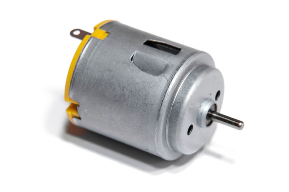
Usually, the DC motor or a Direct Current Motor is by far the most common design of motors out there. A DC motor features two leads; one negative and the other one positive.
When you connect the leads directly to a battery, you will be able to see the motor rotate. Furthermore, when you switch the leads, your motor will start rotating in the opposite direction.
However, you should avoid driving your motor directly from pins on your Arduino board. This is because it may cause damage to your Arduino board. As a result, you should consider using a driver Circuit or commonly referred to as IC.
Requirements
When it comes to running your motor on an Arduino board, you will require the following essential tools:
- An Arduino board of any kind (preferably Arduino Uno)
- DC motor
- Jump wires
- 2.2k ohm resistor
Setting up the model
In order to power your motor, you will be required to send 5-volt through the motor and go to the ground. The voltage will help in spinning your motor; however, you will need to control it. For you to control your motor’s power and rotation, you will have to place a transistor after your motor.
A transistor is a switch that is electrically operated, which can be activated by digital pins in an Arduino board. In this sketch, pin 9 of the Arduino board is used in controlling the transistor-like LED, allowing you to turn your motor circuit off and on.
The circuit will operate; however, it allows chances of designing reverse current due to the momentum of your motor while slowing down. When the reverse current becomes generated, it will move from the negative side of your motor and find its way to the ground.
The route will be via a transistor or an Arduino. Since you will not know what might happen, you will need to offer a way in which you can control the excess current. The best thing to do is set a diode across your motor.
Ensure that it faces the source of voltage; this will be forcing voltage via your motor, which is something you want. When the current becomes generated in the opposite direction, it will be blocked from flowing into your Arduino.
Connecting your motor to Arduino
When connecting the motor to an Arduino board, you should consider building the circuit from pin 9 on your Arduino. Design an Arduino sketch and save it using a memorable name like yourMotor and then key the right code.
Once your sketch is done, you should save it and then press the compile button in order to check the code. An Arduino environment will check the code for you and any syntax error and then highlight it in a message area. Some of the common mistakes you might encounter include missing semicolons, typos, as well as case sensitivity.
When your sketch is compiled correctly, you will go ahead and upload it to the Arduino board. While uploading, you will be able to see the motor spinning for a second and then stop for another second continuously.
However, if it fails to go as planned, you should consider double-checking the wiring:
- Ensure that you are using pin 9 on your Arduino board
- Assess and ensure that the diode is facing the right direction; ensure that the band faces the 5-volt connection.
- Assess the connection on the breadboard. In case the jump wires or a component is not connected with the right row in a breadboard, they will fail to operate.
Connect the components! 🙂

A sketch breakdown of motor
This sketch is very basic, and you will come to notice that it is a variation on the blink sketch. The example discussed here will change the hardware; however, it uses the same code to control LED. The first thing is that the pin should be declared using Pin 9, which is a digital pin. In the setup, pin 9 will be defined as an output.
The loop will tell the output signal to go to high and wait for 1000mS or 1 second and then go to low and wait for another 1 second and repeat the sequence. This scenario will give you the most basic of motor control; it will be telling your motor when to go off and when to go on.
How to control the motor?
To control the motor using your Arduino board, you will require the following:
- A varying supply of voltage
- Varying flux and varying current through the field winding
- Varying armature voltage and varying armature resistance.
With these in place, you will be able to have full control of the motor on your Arduino board.
Final verdict
Running a motor with an Arduino is relatively easy; all that is required of you is to have the right tools and follow the tips discussed in this article. As you can tell by now, the whole process is pretty much straightforward and does not require any advanced skills for you to connect a motor with an Arduino board.
As we come to a conclusion, we hope that you find this article very helpful and that we have answered the question; how to run a motor using an Arduino board?
