
Grounding rods (also known as grounding electrodes) are a key component of a safe electrical system. A rod connected to a structure and then inserted into the ground nearby helps disperse dangerous surges by sending them into the ground instead of back into the electrical panel.
This is vital because uncontrolled electricity flowing back into the system could cause a fire, damage any appliances plugged into it, or even electrocute you if you come in contact with an outlet or wire.
Each grounding rod needs to have a certain resistance threshold, measured in ohms. You might know that electricity flows on the path of least resistance. Therefore, the least amount of resistance in a grounding rod, the easier it will be for it to disperse electricity into the ground. Hence the better the protection it can provide.
Typically, it’s advised to test the ground rod resistance levels at least three times per year at odd intervals to determine how the system might perform in every season. This is where a multimeter comes in. Let’s look at grounding rods and how a multimeter can help them work more efficiently.
Achieving a Low Resistance
The materials used to make ground rods have an effect on their resistance. However, so does their installation. Generally speaking, the deeper you drive a ground rod into the earth, the lower the resistance. Why?
More depth allows the ground rod to create additional flow paths for the electrons. Thus, the electrode is categorized as having less resistance. For instance, if you were to double the depth of a rod, you could reduce the resistance by up to 40% under optimal conditions.
That said, some soil conditions may prevent you from driving the ground rod as deep as you need it to be. In these situations, it’s possible to install multiple ground rods in parallel.
To use this method, you have to account for proper spacing between the electrodes. Understand that the energy displacement around the ground rod is equal to its depth.
For example, a 4-foot deep ground rod would allow current to flow in a 4-feet diameter around itself. It’s important to know this because it helps you determine the correct position of the next electrode. Thus, in this scenario, the distance between rods should be 8 feet to avoid any overlapping discharges. Should the discharges overlap due to a shorter distance between the rods, the resistance wouldn’t be lowered.
In most residential areas, it’s recommended that ground rods maintain resistance of 25 ohms.
Despite needing specialized equipment to conduct measurements, bringing a specialist in is not mandatory when taking the yearly readings. Anyone can do this if they have access to the right equipment and they can save money in the process.
Taking Measurements
Although some may be tempted to use a multimeter that features a resistance socket, that’s not an optimal approach. A multimeter with this feature is fine as long as you’re measuring the resistance of an outlet.
However, for testing the ground resistance of a grounding electrode, it’s best to use specialized equipment.
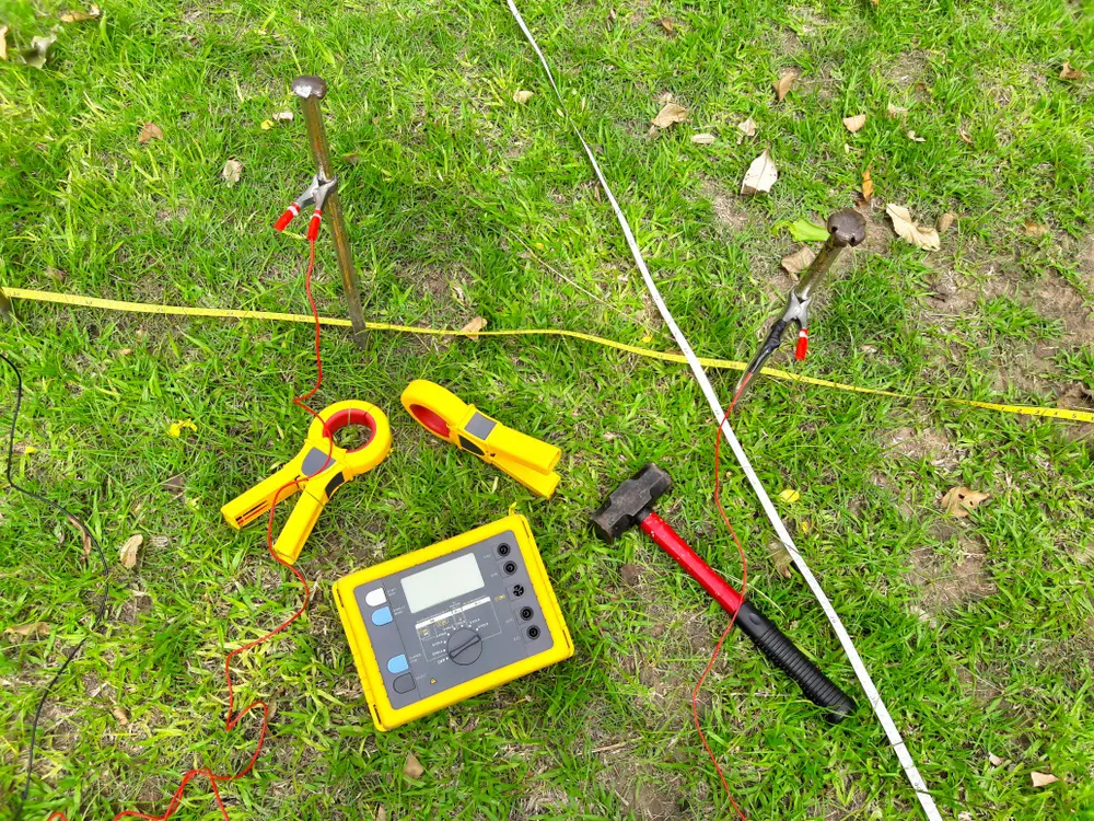
Clamp-on ground resistance testing is a quick and increasingly popular alternative for ground resistance measurements. It uses a specialized device that’s handy when you have limited space or access to the ground.
It’s also helpful in scenarios that prevent disconnecting the grounding system. These devices, known as clamp-on testers, offer a significant advantage. They don’t require powering off the system to measure the resistance.
Furthermore, a clamp-on tester allows the user to take resistance and continuity readings for a ground rod, thus verifying the integrity in rapport to the entire system.
To take a reading, simply attach the clamp-on tester to the rod or the wire leading to the grounding rod. Typically this involves merely pressing a lever to open the clamp.
Make sure that you’re connecting the instrument closer to the topsoil whenever possible. It will improve the accuracy of the measurement more than having the device clamped at the top of the rod. Depending on your tester design, you may have to turn on the meter after establishing the connection.
Also important is to verify that the instrument is set to measure ohms.
Note that these devices have a unique design. Each instrument comes with two shielded assemblies. One of the sides, or clamps, acts as a transmitter. This feeds a test signal into the system at the ground rod location.
The other side is a detector capable of measuring the current flowing through the ground rod.
This technology enables clamp-on instruments to measure the electrode resistance in a variety of grounds: transformer grounds, service entrance grounds, transmission tower grounds, etc.
When to Use a Multimeter
A versatile multimeter can often measure voltage, amperage, resistance, and even continuity in various circuits.
But in this case, it’s best used to check outlets for proper grounding. That means checking to see if there’s a voltage. No voltage indicates that something’s wrong with the electrical system.
To check for grounding, you can connect the multimeter’s probes to the corresponding sockets on the device. Turn the dial to set it to the highest voltage range. Insert the test proves into the outlet by connecting them to the hot and neutral parts.
Alternatively, you could also use a multimeter to check the resistance between the ground electrode and a specific reference point.
Perform Regular Testing
Taking multiple resistance measurements throughout the year is important for personal safety. You’ll want to know to make sure your grounding system is not disconnected and is operating under optimal parameters.
If the installation was done perfectly, the chances of electrical mishaps should be minimal. That said, it’s important to understand that weather conditions and changes within the soil can alter the ground rod resistance effectiveness.
Temperature fluctuations, rain, snow, and other factors can slightly alter the resistance over time. So, for a proper configuration of the grounding system, you’ll need measurements taken during different seasons.
