
A relay now controls most of the electrical components in a car or any other machine. So, there is a possibility a relay in your connections is faulty in case a component is not working. There are little necessary investigations that should be conducted before determining whether the relay is defective or not.
What is a relay?
A relay is an electric device installed in the electrical system of a vehicle. It allows a low current circuit to control one or more loops of higher current. It isolates the high voltage circuits and protects the small current circuit by bringing in an electromagnetic coil to control the course. You can use a multimeter to conduct a test on the coil and the solid-state in a relay.
What is a multimeter?
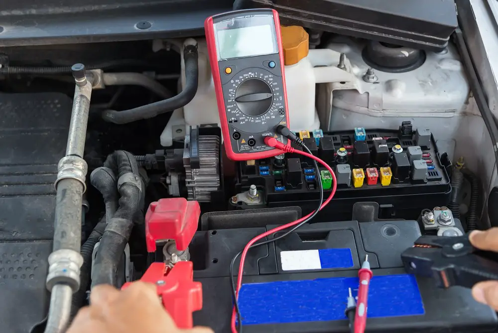
A multimeter is an electric device used to measure voltage, current, and resistance. There are two types of multimeters, i.e., analog multimeter and digital multimeter. In our case, we will dwell much on a digital multimeter, which has more advantages over the analog multimeter. Some of the benefits are that they are simple to use and cheaper. Below is a guide on how to test a 5-pin relay switch.
A 5-pin relay has two pins that control the coil, and the rest three pins switch power between circuits. The three pins have both (NO) normally open and (NC) normally closed connection pins. When the two pins that control the coil activates, normally closed pins will switch to normally open terminals. Below is the test that should be conducted on a 5-pin relay,
1. Testing the relay’s coil
To get the coil’s resistance, you need to refer to the datasheet where you will also get the coil’s tolerance value. Note if the resistance value is 320Ω and ± 10% is the tolerance value, then what should reflect as the resistance value should be between 288Ω – 352Ω. tttt
Adjust your multimeter to ohmmeter settings and connect both lead probes to it. You don’t have to worry about which probe should go to which port. It’s because what we are trying to get is the resistance and polarity does not affect resistance. Read the resistance on the display screen. If the readings fall within the range stated on the datasheet, it only confirms that the coil is good. It the readings are not within the range, i.e., very high or very low, then the coil has a problem. The coil is not repairable, and so you are only left with the choice of replacing it.
2. Testing the relay’s terminal
After we have examined the coil and found the results, now its time to check various terminals on the relay. Measuring the resistance between the terminals is the best way. I will guide you on testing the following;
- Normally open terminal
- Normally closed terminal
- Common terminal
Testing normally open terminal
Here is a guide that will help you through when testing the normally open terminal.
- Set the multimeter to reads resistance, i.e., It should be in ohmmeter setting.
- Connect one of the probes on the multimeter to the COM terminal and the other probe on the normally open terminals. You don’t have to worry about polarity as what we are measuring is resistance.
- Note the readings on the multimeter screen.
The value of the resistance should be several milliohms. This indicates that the normally open terminal is not faulty, and it’s working. In a case where you will get a high value of resistance, i.e., much higher than the several milliohms, this indicates that the normally open terminals are working. The opposition between COM and the open terminal should be high as the two are not connected. So, if the reading on the screen indicates a continuity, i.e., a zero resistance, then the terminals are faulty.
Testing the normally closed terminals
If there is no voltage closing through the normally closed terminal, then the resistance between the COM and normally closed terminals should be zero ohms or very close to zero. At zero ohms normally closed terminal should be working fine.
Below are steps to go by when conducting attest on the normally closed terminals
- Adjust your digital multimeter to ohms settings
- On the normally closed terminal, place on of the multimeter’s probe and the other probe on the COM terminal.
- Note the readings on the multimeter screen.
The reading should be zero. In case there is a high resistance between the normally closed terminal and COM, then the normally closed terminal is faulty.
Testing the common terminals
The common terminals are labeled as 85 and 86. There should be very minimal resistance between the two terminals.
Here is a guide that will help you step by step when conducting a test on the common terminals
- Adjust your digital multimeter to the ohms setting
- On one of the common terminal place one probe and the other probe on the other terminal.
- Note the readings.
If the resistance is very minimal or close to zero, then the two terminals are working well. Higher resistance will indicate that the two terminals are not in connection with which they should be. The reason where the multimeter will indicate a resistance is that the common terminals are linked to each other by a coil. The coil may influence resistance, but it should not be very high.
Like I had noted earlier, relays are unrepairable. You replace them with a working one. A relay switch is not a fuse so, if you are stuck because the normally open terminal has a higher resistance, you can close the voltage from one the COM terminal to the normally closed using a thin wire before getting to a place where you can replace the relay.
Conclusion
The article has guided you through very well, and I am sure now you can conduct a test on the 5-pin relay by yourself. By now, you should have noted that the standard terminals act as normally open terminals, and hence the test is the same. You can now go at trying it on your vehicle.
