
The flow of electrons through a good conductor is what brings about electricity. The electricity is carried in electrical devices built up of components of a specific function. Components such as inductors, capacitors, and resistors are the most common.
Each component has measurable quantities such as current, resistance, and capacitance. The quantities measurements are in amperes, volts, and ohms. The article will focus on volts. Voltage is the electric potential difference between two points and can be measured using a fluke multimeter.
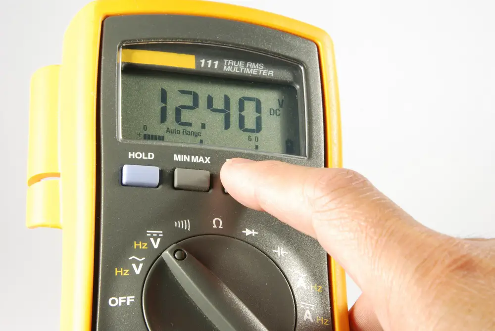
A Fluke Multimeter
Fluke multimeter is a digital multimeter model that is capable of measuring resistance, current, and voltage in an electrical appliance. Four components will be seen on the face of a fluke multimeter;
- A digital display screen could be LED or LCD.
- It has Buttons for various functions, including the on/off switch.
- There is a rotary knob or a dial to select measurement value.
- Also, have several Sockets where the probes are connected.
Digital multimeters such as fluke multimeter can be used to measure voltages both for alternating current and direct current. Here are the pros and cons of fluke multimeter
Pros
- It is more accurate and simpler to use.
- It has eliminated the parallax error
- It doesn’t wear out as there are no moving parts
- No zeroing is required after every reading
- They have the capability of processing and recording the data displayed
- Its digital display has eliminated inaccurate readings
- Apart from measuring continuity, current. Voltage, and resistance they can also measure the frequency
cons
- its display entirely depends on battery
- records error in case of transients
- They are prone to overheating in case of higher voltages
- It has a limited range if the limits are increased the meter get damaged
Below is a step by step guide on how to use a fluke multimeter to measure voltage:
Measuring voltage in an alternating current circuit
- Set your fluke multimeter to measure voltage. ῠ is a visible sign on the multimeter where the dial should be. Some of the digital multimeters operate on an auto range mode, where they will select the range automatically. But for them that you have to choose a range, do it according to the possible volts in the circuit. Preferably set it at the highest possible range, the multimeter can accommodate.
- Connect the black (negative) lead to the common socket (COM). Note that alternating current does not have polarity.
- Insert the positive lead in the voltage socket labelled (VΩ). After you are finished, you can turn on the multimeter and check if it is working by connecting the black and the red probes. The reading on the screen should be 0.5 and less for a proper functioning multimeter.
- Connect the probes to the circuit you want to test simultaneously. To get the correct reading, you should avoid any human contact or other external contacts with the tip of the probe.
- Note the reading on the screen, which is in volts. The reading indicates the number of volts between the two points.
- Withdraw the probes starting with the red one and then the black one.
With the data now, fluke multimeter can help you analyze your test. It has a range button that, when pressed during the analysis, will select a fixed and specific range. The hold button will capture and record a stable reading. When recorded, you can access the readings after the test. A max/min button that will help achieve the highest and the lowest readings. You can also set a reference value for your multimeter by pressing the REL button.
Note when conducting a test on an alternating current circuit, you should avoid mistakes such as jacking the positive lead on the amperes port rather than the voltage port and interchanging the probes.
Measuring voltage in a direct current circuit
- Set the knob or the dial to measure direct current voltage. ῡ is the sign that will appear on the display screen. There are digital multimeters that are capable of selecting a range automatically. But if you have to choose a range and you are not certain, choose the highest possible range a multimeter has.
- Connect the negative probe to the COM port
- Connect the positive probe to the V port. You can test whether your multimeter is functioning well by connecting the positive and negative probe. The reading displayed on the screen should be 0.5 and below when the multimeter is on.
- Attach the probes to the circuit you want to test. Red polarity should be connected to positive and black o ground. To get the correct reading, you should avoid any human contact or other external contacts with the tip of the probe. Fluke multimeter, when testing the DC, it not necessary to connect the probes to their polarity. Incase the polarities are interchanged, the difference will be on display, which will display a negative figure. What you will do is assume the negative sign and record the figure
- Note the readings on the screen. In case the readings fall in the lower range, you will have to detach the probes and connect the red wire to the millivoltage port. Attach the probes again and record the readings.
There is a range button that, when pressed during the test, will select a fixed and specific range. The hold button will capture and record a stable reading. When recorded, you can access the readings after the test. A max/min button that will help capture the highest and the lowest readings.
You can also set a reference value for your multimeter by pressing the REL button. Note when conducting a test on a direct current circuit, you should avoid mistakes like conducting the test when the circuit is powered to voltages higher than it can hold.
Conclusion
By measuring voltage, you will get to know the voltage at a given point, and you can also ensure that it at a proper level. Voltage in alternating current can vary to a range of -10% – 5% and still be okay, but for direct current, even a little difference is trouble. Satisfactory sums of DC voltage difference hinge on the application.