
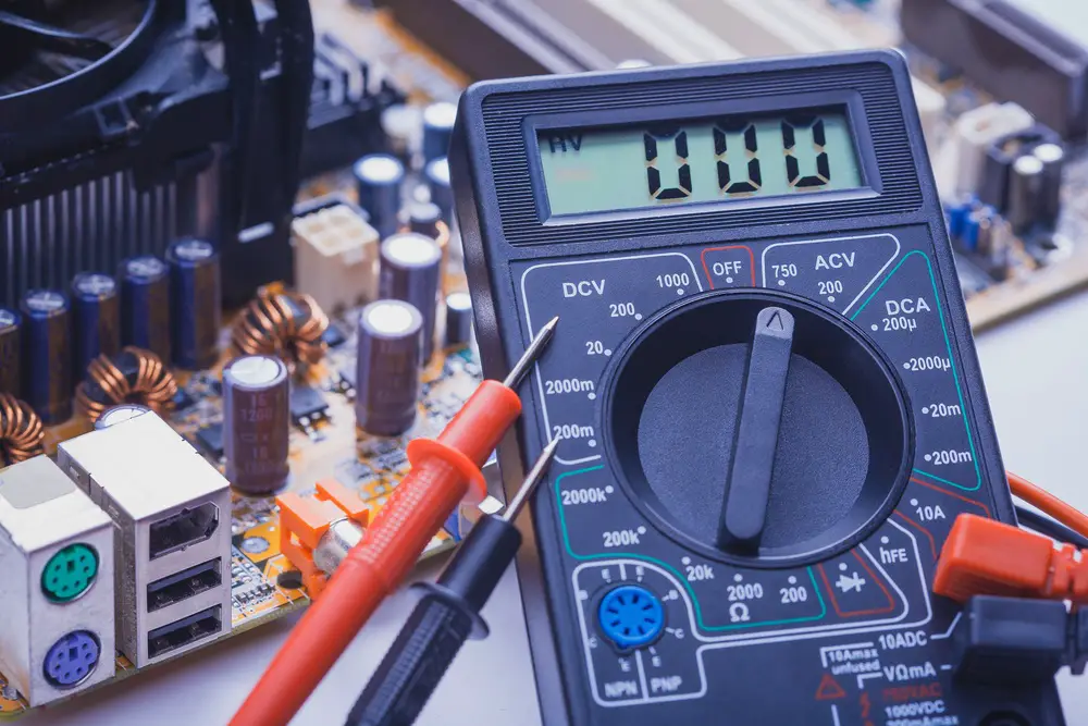
A digital multimeter is described as an instrument used to record electric values. It’s straightforward to use and displays readings on LED or LCD screens. It makes noting down of measurements more accurate. A 7-function digital multimeter tests and measures among them direct current (DC), voltage, AC voltage, resistance, continuity, transistor, and battery on various electronics.
- Measuring DC using a seven function digital multimeter
- Measuring DC voltage using a seven function digital multimeters
- Measuring AC voltage using a seven function digital multimeter
- Measuring resistance using a seven function digital multimeter
- Measuring continuity using a seven function digital multimeter
- Measuring transistor (hFE) using a seven function digital multimeter
- Conducting a battery test using a seven function digital multimeter
- Conclusion
Measuring DC using a seven function digital multimeter
A 7 function digital multimeter measures DC conductors that have up to 10 amperes. The following are the steps to follow when measuring DC using a seven function digital multimeter.
- Position the switch selector to read 10 amperes. It is essential to start with the maximum range if the amperage is not known.
- Plug the positive lead into the 10A top jack. Then insert the negative lead into the COM bottom jack.
- Very keenly, using the tips of the probes, touch the exposed conductors to measure the amperage. It is important to note that amperage is tested in series with the circuit under test.
- Note down the readings. Change the red lead to the center jack if the measurement reads below 2AMPs and then position the range selector switch to the 200 Ma setting.
- Unplug the test leads once testing is complete and store them with the multimeter.
Measuring DC voltage using a seven function digital multimeters
A 7 function digital multimeter measures DC conductors that have a maximum of 1000 VDC.
- Adjust the function switch to read 1000 VDC.
- Plugin the red lead into the positive jack, and the negative lead into the negative jack.
- Point the positive test probe tip carefully towards the positive end of the circuit then point the negative test probe tip to the negative end of the circuit.
- Note readings on the display screen of the multimeter. To achieve higher resolution readings, realign the function switch to effectively lower VDC readings. The screen of the multimeter will then show the correct value and decimal point.
It is important to note that you should not test DC voltage if the component under test on the circuit is being turned OFF and ON
Measuring AC voltage using a seven function digital multimeter
A 7 function digital multimeter measures AC conductors that carry a maximum of 750 VAC. Here are the steps one should follow.
- Position the switch function to the maximum VAC point, which reads 750 VAC. If the voltage is not known, it is important to always begin with the maximum range.
- Plugin the live lead to the center jack and insert the ground lead to the bottom jack. Then switch on the multimeter.
- Touch the live lead to the live side of the circuit, and the ground lead to the negative side of the circuit. Be cautious and careful to avoid damage or any injuries.
- Note the readings. Position the select or range switch to read the minimum range if the voltage is below 200 volts.
- Remove the test leads if testing is complete.
It is important to note that you should not test AC voltage if the component on the circuit is turning on and off. One should be careful to avoid electrocution.
Measuring resistance using a seven function digital multimeter
A 7 digital multimeter measures circuit resistance that is not more than 2000K ohms. The steps to follow are.
- Position the function switch to read the maximum reading of 2000k ohms.
- Plugin the positive test lead into the center jack. Then plug in the negative test lead into the bottom port. Short circuit the test leads so that the meter can read zero ohms.
- Connect the test probes to the tips of the test leads. It is essential to switch off one side of the circuit under test so that it does not affect the resistance reading.
- Record the resistance reading showing on the multimeter. Position the function switch to the next higher position if the measurement is 1.
- Discharge all capacitors and switch off the power of the unit under test to avoid the risk of electrocution.
Measuring continuity using a seven function digital multimeter
- Switch the dial of the multimeter to test the continuity test.
- Press the continuity button where necessary.
- Plug in the black test lead into the COM jack and the red test lead into the VΩ jack. Once that is done, unplug the negative and positive leads in reverse order, starting with red followed by black leads.
- Connect the leads to the component under test, making sure that the circuit is OFF. It may be necessary at times to detach the element under test from others in the circuit.
- Once a complete continuity is detected, the multimeter beeps, but the multimeter will not beep if there is an open circuit.
- Once you are done switch off the multimeter to save battery
Measuring transistor (hFE) using a seven function digital multimeter
A digital multimeter tests transistors to make sure they function correctly. The steps followed in testing the transistor are:
- Position the range switch to the hFE position. Turn on the multimeter.
- Plugin the transistor pins into the correct hFE jack per the Emitter, Base, Collector leads.
- The multimeter will indicate the estimated hFE value
Conducting a battery test using a seven function digital multimeter
The seven functions of digital multimeter test the amount of charge left in the battery. Here are the steps to follow.
- Position the multimeter to read 20 DC volts
- Plugin the live lead into the center port, and the ground lead into the bottom jack. Then switch on the multimeter. Short circuit the two leads so that the multimeter reads zero Ohms.
- Point the ground lead onto the negative end, and the live lead onto the positive terminal.
- Note down the measurements.
Conclusion
As discussed in this article, a seven function digital multimeter has seven functions. Hopefully, this article will guide you step by step on how to use a seven function digital multimeter in measuring DC voltage, AC voltage, resistance, continuity, transistor, and battery test.